
Wiring and power
Plan power distribution, connectors, moving cables, current demand, battery checks, and disconnect diagnosis.
wiring carries power and information through a moving machine. A reliable harness keeps connections protected, allows the full range of motion, and makes each device traceable to its controller port.
Electrical diagram
Record battery, main switch, controllers, power distribution, , , and . Label device names, port numbers, connector types, and cable routes. The physical labels should match the robot configuration and names.
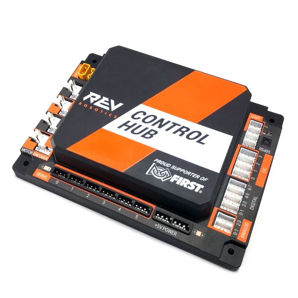
Use 's Robot Wiring Guide as the primary reference, alongside the exact controller and documentation.
Do not copy connector pinouts by appearance. A compatible-looking connector can carry a different or signal order. Check the documentation and third-party sensor compatibility before connecting a device.
Connector retention
Use compatible rated wire and connectors, with the specified termination tools. Provide so a pull on the cable is carried by the structure rather than the terminal. Check seating, retention, , and insulation before power-up.
Route cables away from gears, rollers, wheels, sharp edges, and pinch points. Use enough slack for movement without creating a loop that catches on an object. Sweep each through its complete travel with power disconnected and check combined positions.
Keep service connectors accessible. A replaceable is less useful if its cable must be extracted from every other bundle. Separate power and sensitive signal runs where practical and follow the device guidance for noise suppression.
The connectors and cables guide covers wire selection, crimping, and serviceable harnesses in more detail.
Current demand
Individual tests do not reveal the demand of driving, lifting, holding servos, and feeding at the same time. Make a table of plausible simultaneous actions, then measure representative combined use without deliberately holding stalled actuators.
Voltage loss along a resistive path follows , and heating follows . In an illustrative path with 0.04 Ω total resistance, 10 A produces 0.4 V loss and 4 W of heating. At 20 A, the same path loses 0.8 V and dissipates 16 W. These numbers demonstrate why a poor connection becomes more troublesome at high load.
Select wire size and power distribution from current FIRST requirements and component ratings. Do not raise a fuse rating or bypass protection to make a reset disappear. A high-current fault may begin with a binding slide or a servo commanded into a stop.
Power faults and ESD
A reset during repeated high-load motion can indicate , a poor connection, or a shared supply overload. A disruption associated with contact or movement on a dry surface can involve electrostatic discharge (). Similar symptoms still require diagnosis rather than a guess.
Check the battery, switch, power connections, controller logs, and the action occurring at failure. Inspect retention and wire damage. Follow FIRST's ESD guidance for supported mitigation. Do not improvise direct frame grounding or treat the event field yourself.
Use power faults and ESD for a diagnostic starting table, shared servo limits, and load measurements.
Battery care
Secure the battery against movement and keep replacement access clear. Label batteries and record useful test observations so comparisons are not confused by an unknown power source. Use the approved charger and the battery manufacturer's handling and charging instructions.
Check batteries, leads, and connectors for damage. Stop using a suspect pack until a has checked it. A voltage reading with nothing connected does not tell you how the battery performs under load. Test it during typical robot use, rotate packs consistently, and follow the manufacturer’s handling guidance.
Before an event, verify the switch is accessible, labels match the configuration, cable travel is clear, power connections are retained, and combined motion works with the actual payload. Keep the wiring diagram with the service record.