
Servos
Select servo mode, torque, speed, range, and support while respecting the electrical supply.
A positional uses internal feedback to move toward a commanded angle. A continuous-rotation servo usually interprets the same style of signal as a direction and speed command, so it does not provide the same position control.
Servo requirements
For a gate or wrist, record required travel, load, lever length, move time, holding time, and likely collisions. Confirm whether the device operates in positional or continuous mode and whether programming hardware is needed to change that mode.
Check mounting size, output spline or , horn compatibility, cable length, supported pulse range, and rated supply . Two servos of the same external size may have different travel and electrical requirements.
Torque calculation
Servo is often written in kg·cm, meaning kilogram-force centimeters. Convert it using . It is a torque unit, not the mass a servo can lift regardless of arm length.
For a perpendicular load, . An illustrative 8 N force applied 40 mm from the axis requires N·m before friction or acceleration. Doubling the lever length doubles this demand. In a linkage, the effective lever changes with angle, so evaluate the difficult part of the travel.
A quoted describes a stationary endpoint at a specified voltage. Choose operating margin and validate under repeated load. Do not command the horn continuously into a mechanical stop.
Mechanical support
Mount a pivot or wrist so an external or suitable supported joint carries impact and side loads where practical. Let the servo transmit torque through a horn, linkage, belt, or gear. A long attached directly to its output magnifies collision loads.
Provide a mechanical stop that protects the , then set command limits that avoid driving hard against it. With power disconnected, check the allowed motion; during powered bring-up, approach endpoints cautiously and stop if the servo binds or buzzes under an immovable load.
Speed and voltage
A speed rating in seconds per 60 degrees gives the time for that rotation, so a lower number means faster movement in the supplier’s test. A loaded linkage may move more slowly. Compare servos at the voltage your will supply.
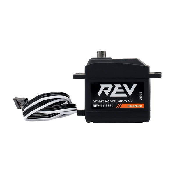
The REV supplies 5 V to servos, with 2 A shared per port pair and 5 A shared across servo and auxiliary 5 V outputs. Those limits mean several lightly loaded servos can work individually yet overload the supply during simultaneous moves. Verify the specifications for your controller revision.
Combined loads
List which servos can move or hold at the same time. Measure the representative combined behavior, including a partially jammed mechanism without intentionally sustaining a . Watch for resets, loss of motion, hot wiring, and servo heating.
If more supply capacity is needed, select an approved solution compatible with the servo voltage and current. Follow the current rules and the device's wiring instructions for power injection and protection; a stronger supply cannot fix an overloaded or bad linkage.
Record the calibrated usable angle range, safe endpoints, mechanism reference position, and any external position feedback. Check the actual horn position; a command alone does not confirm that it reached the target.