
Gears
Match gear standards, calculate pitch geometry, set mesh, and diagnose backlash and binding.
Gears transfer rotation through meshing teeth. They can change speed, , direction, or the axis of rotation, but their locations must preserve the intended tooth engagement.
Pitch geometry
The pitch circle is a reference circle used to describe gear motion. It is not the outside edge of the teeth. For standard unshifted metric spur gears, pitch diameter is , where is module and is tooth count.
For two compatible standard spur gears, nominal center distance is:
An illustrative module-0.8 pair with 20 and 60 teeth has pitch diameters of 16 and 48 mm and nominal center distance 32 mm. Its is . Real mounting design must also satisfy the gear maker's mesh and requirements.
Match module or diametral pitch, pressure angle, and the manufacturer's compatibility requirements. Matching tooth count or outside diameter alone is insufficient.
Direction and stages
Two external spur gears rotate in opposite directions. An intermediate idler gear reverses direction again and bridges space; its tooth count cancels out of the overall speed ratio in a simple gear train.
An idler is different from a compound stage, where two different-sized gears share an intermediate shaft. Compound stages multiply reductions. A 3:1 first stage followed by a 2:1 second stage produces 6:1 overall reduction, with losses at each stage.
Backlash
is between mating teeth, visible as a small amount of output movement when input direction reverses. Too much can harm positioning; removing it by forcing gears together can cause friction, noise, and wear.
Check rotation over a complete revolution, not at one position. Eccentric mounting, a bent shaft, or a warped gear can make the tightest point bind even when the rest of the mesh feels loose. Set the mesh using the manufacturer's guidance and supported shaft locations.
Material compatibility is specific to the chosen gear pair. Use combinations approved by their manufacturer. Do not assume that every plastic-metal pair is unsuitable or that any two metal gears will work together.
Tooth shape
An involute tooth profile is generated by unwinding a taut line from a base circle. The base circle is smaller than the pitch circle. Matching involute profiles transmit a constant angular-speed ratio because the contact force follows a line of action through the pitch point.
The pressure angle is the angle between that line of action and the tangent to the pitch circles. It affects the load pushing the shafts apart. Match the specified pressure angle as well as the tooth size; two gears that appear to fit can still have incompatible profiles.
Gear forces
Gears push on each other as they transmit torque. Those forces load shafts and and can separate flexible plates. Support shafts so the mesh remains aligned under the intended torque; a smooth unloaded is not sufficient evidence.
For a spur gear transmitting torque at pitch radius , the tangential tooth force is . At pressure angle , the radial separating force is:
An illustrative 0.9 N·m torque at a 30 mm pitch radius gives N. At , N. This is a load on the shaft supports even when the turns at constant speed. The calculation assumes ideal spur-gear contact; it does not establish allowable tooth load or bearing life.
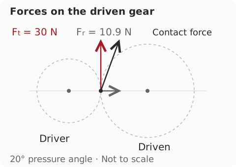
For a diagnostic test, mark both gears, inspect the mesh unloaded, then test the mechanism with a gradually introduced safe load. Stop if teeth skip or the plates separate. Look for loose hubs, cracked bores, rubbing faces, and debris before attributing the fault to .
Use an or external at the output when the task needs position evidence beyond the 's internal transmission. Control can compensate for some repeatable behavior, but it cannot restore teeth that are no longer engaged.