
Belts and chain
Choose compatible transmission parts, calculate ratios and belt length, and design alignment and tension adjustment.
Timing belts and roller chain transfer rotation between separated . Their reliability depends on compatible teeth, shaft alignment, sufficient engagement, and a controlled way to adjust tension.
Belt and chain selection
| Transmission | Useful properties | Design burden |
|---|---|---|
| Timing belt | Low mass, no metal link lubrication, quiet operation | Fixed belt lengths, tooth profile, tension, wrap |
| Roller chain | Available link-length adjustment, durable power transfer | Correct chain standard, lubrication where specified, alignment, retention |
| Direct drive | Few external parts and compact | Output support, fixed gearmotor ratio, exposure to shock loads |
Compatibility
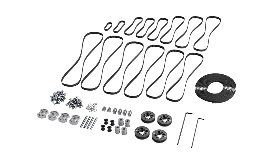
Pitch is the distance between neighboring belt teeth or chain pins. Match pitch, tooth profile, width, and the manufacturer's permitted combinations. Two 3 mm-pitch belts with different profiles are not necessarily interchangeable.
For a chain, match the chain designation and sprocket geometry. Keep inch and metric standards separate. Also confirm bore, hub, shaft, and mounting compatibility.
For either transmission, define as driven tooth count divided by driver tooth count. An open, ordinary two-pulley belt run or two-sprocket chain run turns both shafts in the same direction. More complex routing needs its own direction check.
Length and center distance
A belt's pitch length is its tooth count multiplied by pitch. A common approximation for a simple open two-pulley run is:
Here is shaft center distance and are pulley pitch diameters, all in the same units. A pulley's pitch diameter is tooth count times pitch divided by .
For equal 24-tooth pulleys at 3 mm pitch, each pitch circumference is 72 mm. At a 100 mm center distance, the simple geometry gives mm. That is not an integer number of 3 mm teeth. Selecting a 90-tooth belt gives 270 mm pitch length and a nominal 99 mm center distance before the manufacturer's tension allowance.
Use a belt calculator and the supplier's timing-belt handbook for actual selection. The approximation does not cover arbitrary idlers, crossed runs, or the full load rating.
Tension and support
Slots, an adjustable mount, or a correctly designed tensioner can accommodate installation and wear. Avoid a design in which tension is set by bending a shaft or spreading structural plates.
Too little tension can allow skipping or derailment; too much loads and raises friction. Follow the component specification instead of tightening until the run feels rigid. Check wrap on the smaller pulley or sprocket: a large ratio or poorly placed idler can leave too few teeth engaged.
Keep pulley or sprocket aligned. Add appropriate flanges, guides, and guards where the design calls for them. Plan how a closed belt can be installed and replaced without dismantling unrelated .
Load testing
Mark adjustable mounts, run repeated loaded reversals, and inspect tracking, tooth engagement, tension, and mounting movement. Chain joining hardware must be correctly installed and retained according to its manufacturer; use compatible tools when shortening a chain.
If a transmission skips only at an endpoint, inspect hard-stop impacts, acceleration, tension, and shaft flex before selecting a different material. Keep fingers, loose clothing, and cables outside the pinch points during powered tests.