
Motors and gearing
Calculate reduction, speed, torque, power, and a loaded motor operating point without confusing free speed and stall torque.
A 's useful output depends on the load and the transmission between it and the . Gearing trades rotational speed for ; it does not create mechanical power.
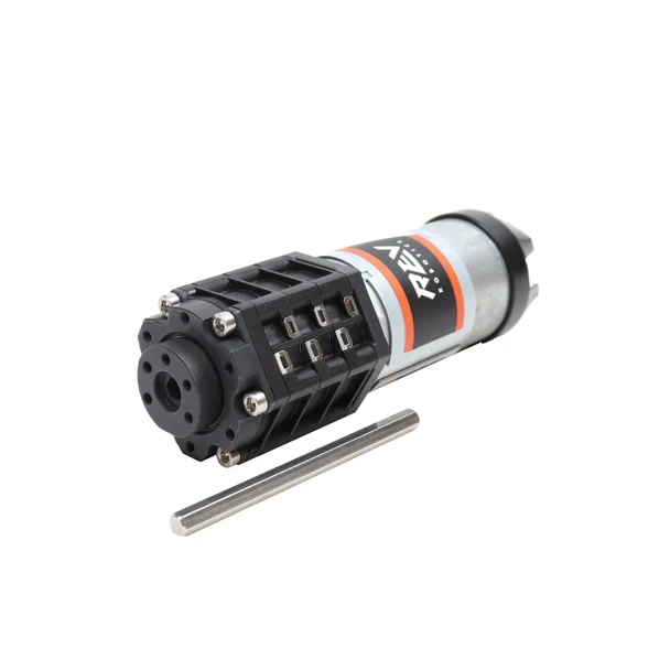
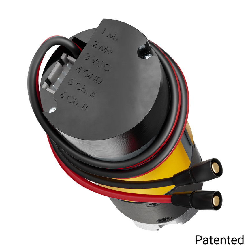
Gear ratio
Here, means input speed divided by output speed:
For a simple gear, sprocket, or toothed-pulley pair, is tooth count. A 16-tooth driver turning a 48-tooth driven part has . The output rotates once for every three input revolutions.
Ignoring losses, and . With transmission efficiency , use . Multiply reductions for stages that share intermediate . Include the gearmotor's internal ratio and any external reduction.
Ratio conventions vary between references. Use the explicit definition above for both speed and torque calculations.
Motor operating points
is the speed with very little external load. is torque at zero speed, where current and heating are high. A motor cannot provide its free speed and stall torque simultaneously.
A simplified brushed DC motor model at fixed is:
Mechanical power is , with for in . Power is zero at both idealized endpoints: at free speed the external torque tends toward zero, and at the speed is zero. The model's peak power occurs halfway between them. That point is not automatically a safe continuous operating point; thermal limits, ratings, and still apply.
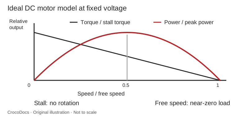
The figure is a mathematical illustration, not a measured curve. Use supplier test data for your voltage and gearmotor.
Drivetrain comparison
Suppose a gearmotor output has a stated no-load speed of 300 RPM and drives a 96 mm wheel through a further 2:1 reduction. Ideal wheel speed is 150 RPM. Ignoring slip:
If that output shaft supplies an illustrative 0.6 N·m at a particular loaded operating point and the external stage is 85% efficient, wheel torque is N·m. At radius 0.048 m, the corresponding tangential force is N. Do not pair this loaded torque with the no-load speed to claim the 's actual operating performance.
Actual acceleration also depends on robot mass, traction, battery voltage, other loads, and rotational . Compare complete drive tests rather than selecting a ratio from top speed alone.
Motor selection
Estimate the required output force or torque, desired motion speed, travel, and duty . Then select a reduction that places the motor in a useful loaded range. Check shaft compatibility, gearbox torque, shock loading, available mounting space, and resolution at the final output.
A gearmotor's advertised ratio may be nominal. Use the exact ratio for distance and angle calculations, especially when adding encoder feedback. Check the manufacturer's stage ratios and load limits.
Stop a test when motion stalls, a transmission skips, or the heats abnormally. Sustained stall is not a valid way to demonstrate a successful lifting design. Check current, temperature, loaded speed, and battery voltage during representative repeated use.