
Fits and tolerances
Distinguish nominal dimensions, clearance, interference, and tolerance stacks, then calibrate fits with test parts.
A is the allowed variation in a . A fit describes the resulting relationship between mating parts, such as a and a hole.
Nominal and actual size
Two features modeled at exactly the same diameter have no specified allowance for manufacturing variation. A sliding shaft needs ; a retained may need a different housing fit. The required relationship depends on function, material, load, and how the component is retained.
In a , the smallest allowed hole remains larger than the largest allowed shaft. In an , the fitted part is larger than its mating opening over the specified relationship. A transition fit may produce clearance or interference depending on the actual dimensions.
Printed and cut features can differ from . Treat published example allowances as starting ideas, not universal manufacturing specifications.
Dimensional limits
Suppose an illustrative shaft measures mm and a hole is specified as mm. Minimum diametral clearance is:
Maximum diametral clearance is mm. Those numbers describe clearance across the diameter; radial clearance is half that value for concentric parts. They are not a recommendation for a particular bearing or manufacturing process.
For bearing seats, use the bearing and housing supplier's fit recommendations. For a removable printed spacer or guide, print a coupon and test the actual mating hardware.
Tolerance stacks
A combines dimensional variations that affect a final relationship. If three spacers are each mm long, the worst-case stack is mm. A bearing with less available allowance may bind at one end of that range.
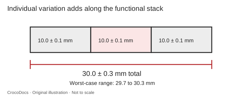
Worst-case addition is conservative and useful when any allowed combination must assemble. Statistical methods need justified assumptions about manufacturing distributions and independence; they do not replace controlled measurements in a small team-built assembly.
Locate critical features from common to reduce unnecessary chains. Use a controlled shim, adjustment, or compliant feature where variation must be accommodated. Do not make every hole tighter when only one alignment relationship matters.
Process calibration
For a printed fit coupon, create several labeled hole sizes around the intended diameter and print them with the final material, orientation, and settings. Measure with suitable tools, then test the actual shaft or . Record which dimensions give the intended function.
Recheck when the printer, material, nozzle, orientation, or relevant settings change.
For laser cutting, is the material removed by the cut. For milling, tool diameter and runout affect features and corners. Ask the fabricator which compensation it applies. Adding your own correction on top of its correction can move the result in the wrong direction.
Fit inspection
Measure critical stock thickness, hole location, and support spacing before tightening an assembly. A screw used to pull misaligned plates together can hide the error while bending a shaft or preloading bearings.
Record a fit by its measured result and function, such as "removable by hand with no noticeable rocking," as well as its nominal CAD value. For experienced teams, place critical tolerances on the released drawing and inspect the first manufactured part before approving the rest of the batch.