
Shooting on the move
Account for robot velocity, launcher offsets, and release delay when aiming a moving FTC shooter.
A ball leaves a moving with some of the robot's velocity. To hit the same target, the launcher must account for that motion. Start with a repeatable stationary shot and a trustworthy velocity estimate before adding this compensation.
The projectile guide covers launch angle, speed, and flight time. This guide adds horizontal robot motion while assuming the launcher stays at a fixed height on a level .
Release position
The robot moves between requesting a shot and the ball leaving the launcher. Measure that release delay separately from the ball's flight time.
For a short delay and approximately constant velocity:
Here is robot position, is velocity, is heading, and is angular velocity. Predict the launcher position using that heading and its mounting offset. Faster acceleration or a long feeder delay makes this approximation less reliable; improve the prediction or limit when the robot shoots.
Use measured field-relative velocity, not joystick commands. If your localizer reports robot-relative velocity, rotate it into your chosen field axes first. Keep positions in metres and angular velocity in radians per second throughout the calculation.
Camera latency is a separate issue. Match a camera observation to the robot pose at its capture time, or let the localization system do that. Once you have an updated present-time pose, adding the same camera delay again predicts too far ahead.
Launcher velocity
Turning moves a launcher that sits away from the robot's centre of rotation. Let be the release point's horizontal offset in field coordinates. Its velocity is:
Rotate a robot-fixed offset into the field frame at the predicted release heading before using it here. If a turret's muzzle is offset from its own rotation axis, its rotation adds another velocity contribution. A launcher moving vertically on an arm also needs vertical release motion included; the equations below do not include it.
Aim and speed
Let be the horizontal vector from the predicted release point to a stationary target, its height difference, and the chosen flight time. The ball's velocity relative to the launcher, , must be:
Calculate the field-relative yaw from . Calculate pitch from and speed from the length of the three-dimensional velocity vector.
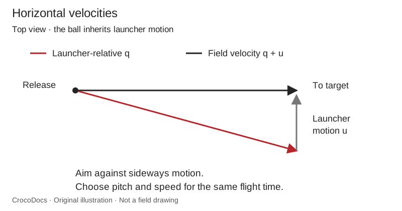
For example, take a target 2.4 m ahead and 0.7 m above release, with a 0.6 s flight. If the launcher moves sideways at 1 m/s, the required relative velocity is approximately m/s. That gives a yaw of −14.0°, pitch of 44.9°, and speed of 5.82 m/s. The sideways components cancel in the field frame.
The calculation changes both speed and pitch; changing yaw alone does not preserve this shot.
Java helper
Download MovingShot.java and place it in your TeamCode source folder. Add your team's package declaration if needed. The file uses 8 and has no SDK or library dependencies.
Call it with the target displacement and launcher velocity at predicted release:
Optional<MovingShot> candidate = MovingShot.atFlightTime(
        2.4, 0.0, 0.7, // target displacement: x, y, height (m)
        0.0, 1.0,      // launcher velocity: x, y (m/s)
        0.6);          // flight time (s)

if (candidate.isPresent()) {
    MovingShot shot = candidate.get();
    double fieldYaw = shot.yawRadians;
    double hoodPitch = shot.pitchRadians;
    double ballSpeed = shot.speedMetersPerSecond;
    // Convert through your calibrated launcher settings, then check limits.
}
Import java.util.Optional in the calling file. The helper rejects invalid inputs; it does not command hardware or decide whether a shot is safe to feed. Convert field yaw to your turret's frame using the predicted robot heading and calibrated turret zero. Respect its actual travel and cable limits rather than wrapping every result to an unreachable angle.
Fixed hood
Choosing a flight time freely assumes you can produce the resulting speed and pitch. With a fixed hood angle , time must also satisfy:
Search for a positive solution within a tested flight-time range, then check speed and . A fixed ball speed adds another constraint: the length of must equal that speed. If the launcher cannot produce a feasible shot while moving, slow down or stop before feeding.
Calibration table
A table of successful stationary shots is often a better starting point than a drag-free model. Store , hood setting, and measured flight time together for each distance, ball type, and target height.
You can use that table to estimate a moving shot:
- Start with the flight time for the current target distance.
- Calculate a virtual target vector: .
- Look up a complete row at distance , interpolating its RPM, hood setting, and time together.
- Use the new time to repeat the calculation. Set a small limit and stop when the time changes by less than a justified by your measurements.
- Aim along and use the RPM and hood setting from the matching row.
Reject the shot if the lookup leaves the calibrated range or fails to converge. Do not clamp it to the nearest row and feed anyway. Preserve the table's target height and ball type; a different HIVE state needs an appropriate calibration or model.
This method approximates a stationary shot toward a shifted target. Drag depends on the ball's motion through the air, so stationary calibration does not remove the need for moving tests.
Feeding
Before starting the feeder, check that the pose is recent, the shot lies in the tested range, the turret and hood have settled, and measured flywheel speed has recovered. Account for how long the ball takes to reach release; a solution for the current pose is already late when the feeder has a noticeable delay.
Turret aiming shows the pivot-offset and reachable-angle calculations. Flywheel velocity control turns measured RPM recovery into a separate readiness condition. Establish both with stationary tests before combining them with this moving-shot model.
Keep updating the prediction before the feed is committed. Once the ball is committed, coordinate setpoint changes with its actual release instead of changing the aim unpredictably during contact.
In BIOBUZZ, a CELL can move as the HIVE tips. These equations assume a stationary target during flight. Use the current opening position and orientation, and avoid shooting during an unmodelled transition. A tag detection identifies a reference on the structure; it still needs the geometric transform to the scoring opening.
Testing
Begin at one distance with one ball type. Test a stationary robot, then constant sideways motion in both directions. Add motion toward and away from the target, and test turning only after straight-line motion works.
Record pose timestamps, measured velocity, predicted release position, flight time, requested and measured RPM, and miss direction. A consistent miss on one side can come from a frame or sign error. A miss that grows with speed can come from release delay. Check those before adding an unexplained correction factor.