
Turret aiming
Aim from the turret pivot, convert field bearings to mechanism angles, and choose a reachable turn
Calculate the field from the turret pivot to the target, subtract the heading, then convert that angle into the turret's calibrated reference. Verify this geometry with the shooter disabled before adding automatic feeding.
Reference and feedback
Define which physical direction is turret zero and whether positive movement is counterclockwise. Establish that reference with homing or a suitable absolute measurement. Servo.getPosition() reports the commanded position, not the turret's measured arrival.
A positional can use its internal controller within its configured travel. A continuous-rotation servo needs external position feedback and a controller if you want it to hold an angle. The choice depends on gearing, travel, accuracy, and the servo model; changing modes is not automatically a better controller.
A single-turn absolute encoder cannot distinguish two positions separated by one encoder revolution. Track or recover the full position when turn count matters for travel and cables. See Multi-turn position.
Pivot position
Use one field frame with counterclockwise-positive heading , zero along +X. Let the robot reference position be , and the turret pivot offset in the robot frame be , with +X forward and +Y left. Then:
For a target at , its field bearing is . Aiming from the robot centre instead of the offset pivot introduces an error that varies with position and heading.
If encoder angle zero points at a robot-relative angle , the requested encoder angle is:
Here wrap selects an equivalent angle within one revolution. It does not decide whether that angle is mechanically reachable.
Worked geometry
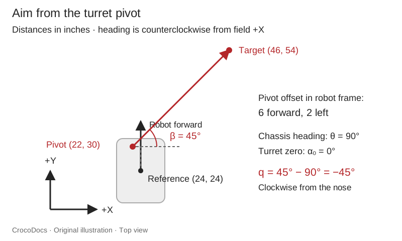
Suppose the robot reference is at inches, its heading is 90°, and the pivot is 6 inches forward and 2 inches left of that reference. Rotating the offset gives , so the field pivot is inches.
A target at is 24 inches along each field axis from the pivot. Its bearing is therefore . With turret zero pointing forward on the , , so the requested mechanism angle is : clockwise from the robot's nose. Convert the example's degrees to radians before calling the helper below.
Reachable turns
For continuous angular coordinates, , , and point in the same direction. A limited turret cannot necessarily travel between them safely. Select an equivalent target inside its calibrated limits and nearest its current unwrapped position.
Save this 8 helper as TurretAngles.java. All angles are radians. An empty result means the target is invalid or unreachable, so leave automatic feeding disabled.
package org.firstinspires.ftc.teamcode;

import java.util.OptionalDouble;

public final class TurretAngles {
    public static OptionalDouble reachable(double desiredRadians, double currentRadians,
                                            double minRadians, double maxRadians) {
        if (!Double.isFinite(desiredRadians) || !Double.isFinite(currentRadians)
                || !Double.isFinite(minRadians) || !Double.isFinite(maxRadians)
                || minRadians > maxRadians || currentRadians < minRadians
                || currentRadians > maxRadians) return OptionalDouble.empty();
        double turn = 2.0 * Math.PI;
        double base = Math.atan2(Math.sin(desiredRadians), Math.cos(desiredRadians));
        double firstTurn = Math.ceil((minRadians - base) / turn);
        double lastTurn = Math.floor((maxRadians - base) / turn);
        if (firstTurn > lastTurn) return OptionalDouble.empty();
        double nearestTurn = Math.rint((currentRadians - base) / turn);
        double selectedTurn = Math.max(firstTurn, Math.min(lastTurn, nearestTurn));
        double target = base + selectedTurn * turn;
        if (!Double.isFinite(target) || target < minRadians || target > maxRadians) {
            return OptionalDouble.empty();
        }
        return OptionalDouble.of(target);
    }
}
For limits of -170° to +170°, a target at 180° is unreachable. Clamping it to 170° would silently aim ten degrees away. Either turn the chassis through a tested action, choose another shot, or withhold the shot. For a wider turret, the helper may choose another equivalent turn, while keeping the commanded path inside the declared interval.
The helper assumes every angle between the two limits is clear. If an arm, , or cable creates an interior forbidden region, validate the entire sweep too. A mathematically reachable endpoint does not establish .
Map the actuator
If using a positional servo, measure two safe turret angles and their commands . Within that calibrated interval, a first linear mapping is:
That calibration includes the gear ratio and direction. It also allows mirrored servos to use different maps. Verify intermediate angles; do not assume a command range of 0–1 means 360° or that two coupled servos have identical zeros. Use the manufacturer's pulse range for that exact servo model.
For a CR servo or , close the angle loop using the external encoder and a verified output sign. Keep full-position travel limits outside shortest-angle wrapping. Stop automatic motion if the reference or becomes invalid.
Aiming tests
Disable the flywheel and feeder. Place a visible target at a measured point and test:
- Known turret angles, including zero and ±90°, to check encoder and conversion.
- Several robot headings at the same position to check robot-heading subtraction.
- Several positions with the same heading to check the field bearing and pivot offset.
- Both sides of the angle wrap and travel limits, including an unreachable target.
- Lost or stale localization, then STOP during a commanded turn.
Record requested angle, measured angle, physical pointing error, and source age. Constant error suggests a zero offset; error that changes with heading suggests a frame, sign, or pivot issue. Backlash and flex can differ by approach direction.
Start with stationary aiming. A moving shot also needs release delay, chassis translation and rotation, and launcher velocity; adding a derivative term to the bearing alone is incomplete. Continue with shooting on the move. If adding Limelight, account for its camera mount and image age before combining its correction with .