
CAD examples
Study FTC drivetrain, layout, and outtake designs with credited images and questions to guide your own work.
Another team's can help you understand a that is difficult to see on a finished . Start with one question, such as how an axle is supported or how a transfer clears the frame. Trace that part of the design before studying the whole machine.
Pretty Smart Robotics
Pretty Smart Robotics, 16441, explains custom using , , belts, and chain. The team breaks the drivetrain down into side plates, , and wheel assemblies, which makes it easier to work through one section at a time.
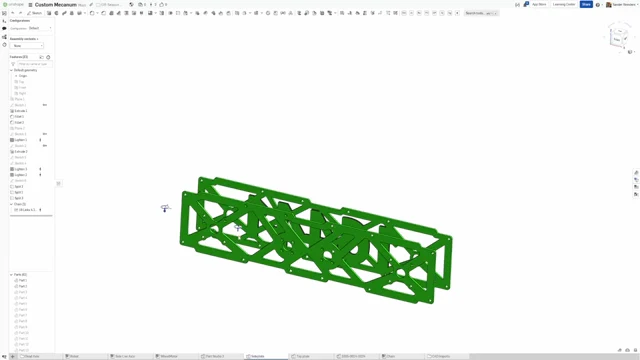
The side plates connect axle supports into a rigid module. Start with the round axle openings and the smaller attachment holes around the plate edges; then look at the material joining those regions. Before choosing the cutouts, leave enough material around those holes to support the axles and attach the crossmembers.
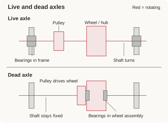
The tutorial's live-axle and dead-axle examples answer a specific question: which should turn, and where should its sit? In the live arrangement the , wheel, and driven sprocket turn together, with bearings in the frame. In the dead arrangement the axle stays fixed and bearings travel with the wheel assembly. A pulley or sprocket must therefore drive that rotating assembly directly.
The team also places the transmission differently in its examples. Putting it away from the robot's central space can leave room for another mechanism, but check overall width and protection. Axle type alone does not dictate that placement.
For your own wheel module, trace two paths separately: from the motor into the wheel, and load from the wheel through its bearings into the frame. You should be able to name the part at every connection.
For your own design, model one complete wheel module first. Include the small hardware and explain how it comes apart. Then use the custom drivetrain guide to check its layout and manufacturing needs.
Hyperion
Hyperion, FTC 9614, describes its CENTERSTAGE outtake design and revisions. The team starts with the desired object position, compares linkage layouts, and checks them against the rest of the robot.
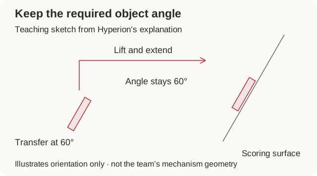
One of the team's early decisions was to transfer pixels already at 60°, matching the angle needed at the backdrop. That let the outtake lift and extend the pixels without adding a separate motion, which would tilt the claw up or down. Transfer orientation removed a job that another would otherwise need to perform.
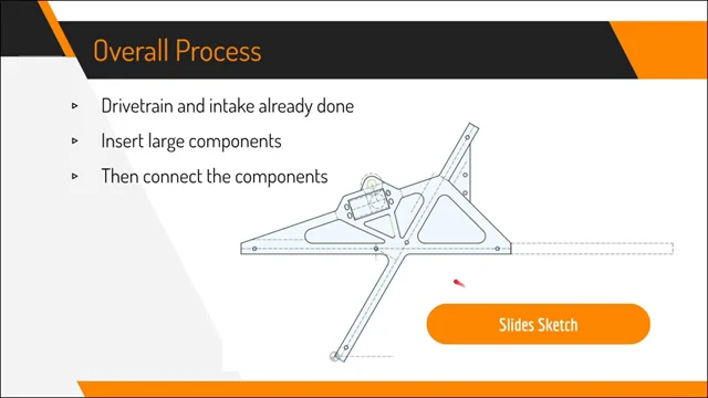
In the CAD view above, the team placed the large slide components before designing the plate that connects them. It compared linkage layouts by checking their height and whether they would hit the climb mechanism or . A side-view let the team check those movements before modeling every part in detail.
After using the robot in competition, the team wanted more reach so the drive base could stay farther from the backdrop. It revised the design with a double-reverse four-bar linkage and made a printed to check the movement. That gave the team a way to test whether the new layout solved the problem before building the complete outtake.
Try the same method with your mechanism. Sketch its important positions, include nearby parts, and compare two possible layouts. Build a simple prototype of the uncertain movement before detailing the final plates.
Seattle Solvers
Seattle Solvers, FTC 23511, demonstrates master sketching with simplified robot components. A master sketch is a shared layout that drives more detailed parts.
The tutorial uses circles for motors and wheels and simple shapes for the hubs. Pulley pitch circles and the distance between their centers set the belt layout. The team brings those sketches into the detailed and uses them to position mounting holes and other features.
This is why a layout change can move the corresponding mounting geometry. A hole that merely has the same typed coordinates is independent; a hole constrained to the shared reference follows it. The drive-layout exercise lets you make that distinction by moving the rear wheel and checking its dependent bearing opening.
Use the team's published CAD collection to explore further. First find the main assembly and shared layout. Hide one subsystem at a time, trace a shaft or game-piece path, and look at where the mechanisms mount and pass game pieces between them. Check the document's stated and revision before comparing it with a robot video.
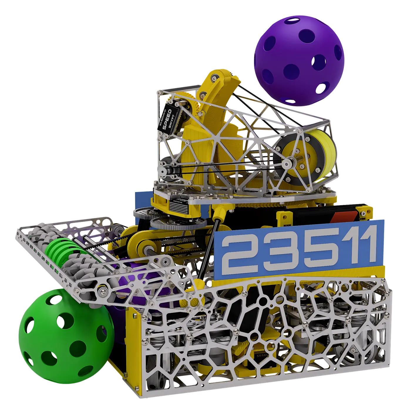
Cypher’s launcher sits on a rotating turret above a compact drivetrain. Check the room it needs as it turns, not just when parked. In a top view, mark the turret axis and draw a circle out to the farthest rotating part. That circle shows space you need to check around the mechanism.
Use the detailed assembly to check differences in height, access, and cable travel. A top-view circle is a useful early check, while the three-dimensional model resolves which parts actually share the same space.
Use an example well
Write down the design decision you learned, the conditions it depends on, and how you would test it on your robot. A plate shape alone does not explain its material, load, , or manufacturing process.
Keep the original team's credit when sharing an image or adapted design. Check the creator's permission or license before redistributing CAD files or derivatives. Public viewing access does not automatically grant every reuse right.