
Forces and motion
Estimate the loads, torque, speed, and stiffness that a robot design needs.
A model can fit perfectly and still bend, , or tip over. Estimate the main forces and movements before choosing an or cutting a plate. Start with a simple ; you can refine the calculation when the design becomes clearer.
Force and weight
A is a push or pull, measured in newtons, written N. Mass, measured in kilograms, describes how much matter an object has. Its weight is the force of gravity on that mass.
Near Earth's surface:
Here is mass in kilograms and is approximately . A 0.6 kg carriage has a weight of about 5.89 N. Moving it upward requires more than balancing that weight: the also has friction and must accelerate.
Draw the forces on the part you are studying. This is a free-body diagram. For a simple carriage, include downward weight, upward lifting force, and the guide reactions that prevent it from rotating or moving sideways. Keep the force directions consistent with the actual mechanism.
Torque
is a force's turning effect about an axis, measured in newton-meters, N·m. A force perpendicular to an arm produces:
is the perpendicular distance from the pivot to the force's line of action, in meters. A 10 N force acting 0.12 m from a pivot produces 1.2 N·m. The same force at 0.04 m produces 0.4 N·m.
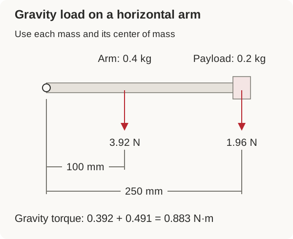
For gravity on an arm, use the horizontal distance from the pivot to each mass's , the point where you can treat its weight as acting. The arm's own mass belongs in the calculation too.
For example, take this horizontal arm:
| Load | Mass | Horizontal distance from pivot | Gravity torque |
|---|---|---|---|
| Arm | 0.4 kg | 0.10 m to its center of mass | 0.392 N·m |
| Payload | 0.2 kg | 0.25 m | 0.491 N·m |
| Total | 0.883 N·m |
As the arm moves toward vertical, those horizontal distances get smaller. Work out where the arm puts the greatest load on the , including when it extends. Allow for acceleration, friction, and forces from anything the arm touches before choosing the hardware.
Reduction and speed
A trades output speed for output torque. For a simple gear or belt pair, divide the driven tooth count by the driver tooth count. A 20-tooth driver turning a 60-tooth driven pulley gives a 3:1 reduction.
Ignoring losses, the output turns one-third as fast and has three times the input torque. With estimated efficiency :
is the reduction ratio, and is rotational speed, such as revolutions per minute (rpm). Efficiency accounts for losses and depends on the real transmission and operating condition.
Suppose a hypothetical actuator can provide 0.30 N·m at the intended operating point. A 5:1 reduction at an assumed 80% efficiency gives about 1.20 N·m at the arm. Compare that with the 0.883 N·m gravity load, then allow for acceleration and other loads. These values illustrate the calculation; select a real actuator from its ratings and performance data.
Do not use as a continuous working rating. Stall means the motor is powered but cannot turn. Current and heating can be high. A mechanism that only works near stall needs a different load, ratio, actuator, or support arrangement.
If the input speed were 120 rpm, a 5:1 reduction would give 24 rpm. That is 144 degrees per second, so a 90° movement would take 0.625 seconds at constant speed. A real move also includes acceleration, deceleration, and load-dependent speed.
Linear movement
A drum converts rotation into cable travel. One revolution takes up a cable length equal to the drum's circumference:
A 12 mm working radius gives about 75.4 mm per revolution. Lifting a 10 N cable load at that radius requires 0.12 N·m at the drum before losses. If the cable stacks into layers, its working radius changes, affecting both torque and travel.
A cascaded lift can move its final carriage farther than its first stage. That extra travel also changes the required force and power. Calculate the forces for the whole cable or belt route, called its reeving, before choosing a motor. Payload weight alone does not tell you the force the motor must provide.
Strength and stiffness
concerns damage or failure under load. concerns how far a part deflects, or bends, while loaded. A plate can survive but bend enough to misalign or miss a transfer.
Follow the load from the point of contact through the supports into the . Shorten unnecessary overhangs, support near their loads, and use section depth or bracing where bending occurs. Adding material far from the bending center can be more effective than making every surface uniformly thicker.
Keep the 's center of mass in mind. A high or extended mechanism can reduce stability during acceleration and braking. A static model of the robot sitting still does not cover those movements.
Use Arms and linkages, Slides and lifts, and the Engineering motor guide to apply these ideas. For an uncertain load, make an adjustable and measure its behavior before committing to the final structure.