
Tolerances and fit
Separate nominal dimensions, manufacturing variation, clearance, and accumulated error.
Two parts with matching nominal may not fit when manufactured. Decide which surfaces locate the parts, how much movement is acceptable, and how the chosen process varies before setting the final dimensions.
A is the stated target. A is its permitted variation. is the space between mating features. For example, you can design a gap between parts and still have variation in the size of both parts.
Start with the intended fit
| Fit | Intended behavior |
|---|---|
| Clearance | Parts assemble with space between them |
| Close sliding | Limited play while still allowing movement |
| Overlapping size limits create a press or other controlled |
The useful fit depends on the material, temperature, load, surface, and process. A housing in machined aluminum and a printed bracket should not automatically use the same allowance.
Use the supplier's fit guidance for bearings, , inserts, and other specified interfaces. For a printed joint, print a small test piece with the same hole or mating shape and measure how it fits.
Diameter and per-side clearance
Suppose an illustrative round shaft is 10.00 ± 0.02 mm, and its opening is 10.10 ± 0.03 mm.
The smallest opening is 10.07 mm and the largest shaft is 10.02 mm. Minimum diametral clearance is therefore 0.05 mm. The largest opening is 10.13 mm and the smallest shaft is 9.98 mm, giving 0.15 mm maximum diametral clearance.
For concentric round parts, the space on each side is half that: 0.025 to 0.075 mm. Do not describe a 0.10 mm diameter difference as 0.10 mm on each side.
These numbers illustrate a tolerance calculation. They are not a recommended shaft fit for every joint. The required behavior determines the fit you specify.
Check the worst combination
Consider a tab 9.80 ± 0.15 mm wide fitting into an opening 10.00 ± 0.15 mm wide. Nominal clearance is 0.20 mm, but the tightest combination is:
smallest opening − largest tab
9.85 − 9.95 = −0.10 mm
A negative result means interference: the allowed parts can overlap by 0.10 mm. The loosest combination gives 10.15 − 9.65 = 0.50 mm clearance.
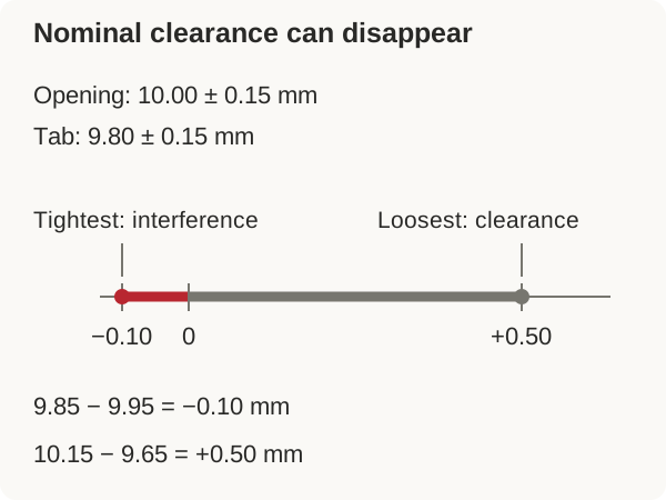
If the opening changes to 10.40 ± 0.15 mm, the resulting clearance becomes 0.30 to 0.90 mm. That avoids interference within these assumed limits, but may create too much play. If that much play is a problem, you could use a process with less size variation, add a feature that locates the parts, or make the joint adjustable.
Do not simply enlarge every opening until the whole fits. Decide where the parts should be located and where clearance is harmless.
Add a stack
A combines variation across several dimensions. For a worst-case one-dimensional stack, add the magnitudes of the contributing tolerances.
One column of the practice plate assembly could have:
| Item | Dimension |
|---|---|
| Lower plate | 3.00 ± 0.10 mm |
| Spacer | 12.00 ± 0.15 mm |
| Upper plate | 3.00 ± 0.10 mm |
| Overall column | 18.00 ± 0.35 mm |
Its allowed overall height is 17.65 to 18.35 mm. That calculation says nothing yet about the two spacers matching each other. If one is 11.85 mm and the other 12.15 mm, their 0.30 mm difference across 40 mm can tilt the upper plate by about 0.43°.
If parallelism matters, choose a process or matching method that controls that difference. A reasonable overall height tolerance does not automatically control alignment.
Choose useful references
Locate critical features from common , the reference faces, axes, or that define the part's position. A bearing pattern should follow the intended shaft axes, not a chain of unrelated outside edges.
Repeatedly dimensioning hole-to-hole distances can accumulate error. A coordinate or baseline scheme from a common reference often makes the intended positions clearer. Avoid duplicate driving dimensions that ask the drawing or to satisfy conflicting definitions.
Check the real assembly too. Clearance screws may let a plate shift before tightening, so the CAD nominal position is not automatically the physical location. Add a feature that locates the plate if that shift would misalign gears or move the place where a transfer delivers the game piece.
Test the manufacturing process
Make a small test piece using the same material, print orientation or machining setup, and settings as the final part. Include the relevant hole, slot, insert pocket, or mating tab. Measure what comes off the machine, then test it with the actual mating component.
Keep the correction separate from the nominal hardware dimension. For example, a variable named shaftDiameter can describe the real shaft, while boreAllowance describes the deliberate CAD adjustment. That makes the reason for the change visible.
Do not scale the whole model to fix one hole. Scaling changes mounting spacing, thickness, and every other interface at the same time. Correct the feature that needs adjustment.
Put requirements on the drawing
Specify tolerances that affect function, using a convention the fabricator understands. Ask what their process can achieve before demanding tighter values. Extra precision can add cost without improving the .
Use Drawings and exports to communicate the dimensions, units, material, and revision. Use Fits and tolerances for the broader manufacturing discussion. After assembly, record any deliberate shimming or fit correction so replacement parts can reproduce it.