
More sketch tools
Make slots, rounded outlines, and repeated holes without losing control of the geometry.
Once you can the two-hole plate, practice the shapes that appear in brackets: slots, arcs, repeated holes, and projected geometry. Keep these exercises in a separate named Sketch tool practice, so the original plate remains unchanged.
Lines and construction geometry
Use straight lines for edges that will become real boundaries. Switch a line to Construction when it is only a reference, such as a centerline or the axis of a hole pattern.
A closed region needs connected boundaries. Two endpoints that appear to touch may still have a tiny gap. Apply Coincident to connect them, then inspect the region shading. Adding thickness will be much easier when you have one clear outline instead of several overlapping loops.
Dimension positions from the or a stable reference. If a hole must remain centered on a plate, constrain that relationship instead of entering a distance that only happens to place it at the center today.
Make an adjustment slot
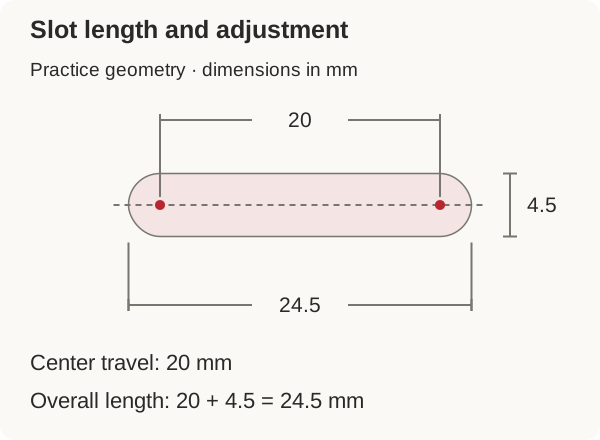
A straight slot has two parallel sides joined by semicircular ends. It lets you slide a screw along the slot to adjust a part’s position. The screw center can travel between the two end-circle centers; the slot’s overall length also includes its width.
Make this practice on the Top :
- Draw a 70 × 40 mm center-point rectangle at the origin.
- Draw a horizontal line with endpoints at X = −10 and X = 10 mm, both at Y = 0. This is the slot's center path.
- Select that line and choose Slot. Set the slot width to 4.5 mm.
- Check that the center path is , so it does not divide the region you will later cut.
- Inspect the two rounded ends. Their centers should be 20 mm apart, while the slot's overall length is 24.5 mm.
The 4.5 mm width here is a practice dimension. A real slot needs a suitable screw fit, material around its edges, and enough room for a washer throughout its movement.
To make a part from this sketch, accept it and the rectangular region 3 mm, leaving the slot region unselected. The result should be one plate with one through slot. A second option is to make the plate first and use an Extrude Remove for the slot.
For a tensioning mount, put the slot direction along the intended adjustment. A long slot in the wrong direction will not change the belt center distance as intended. See Transmission layouts.
Draw a rounded link
An arc is part of a circle. A tangent line meets an arc smoothly, without a corner. These are useful for a link whose outline follows two pivot holes.
In a new sketch, locate two hole centers at (−20, 0) and (20, 0) mm. Draw a 4.5 mm hole at each center. Make their diameters Equal.
Around each center, draw an outer circle of 8 mm radius. Join the circles with horizontal lines above and below their centers. Apply Tangent between each line and the circles it touches. Use Trim to remove the inward-facing halves of the outer circles and any line segments that continue through them.
You should have a capsule-shaped outside boundary, 56 mm long and 16 mm wide, surrounding the two holes. The hole centers remain 40 mm apart. If the outer circles were accidentally dimensioned to an 8 mm diameter, the link will be much narrower; read the radius/diameter symbol before accepting.
Trim changes the entities in a sketch. After trimming, inspect dimensions and constraints again. Restore an intended relationship if its referenced arc or segment was removed. The result should have one continuous outside boundary and two separate hole regions.
Mirror and repeat
Use a when a feature must stay symmetric about a line. For a symmetric two-hole pattern, define one hole, add a construction centerline, and mirror the hole across it. The mirrored hole follows the original.
Use a when features repeat at regular intervals. For example, one 4.5 mm hole at X = 10 mm, repeated at 15 mm spacing with three total instances, gives centers at X = 10, 25, and 40 mm.
Choose one way to control the repetition. A mirrored hole does not also need independent dimensions that force its position. Those extra dimensions may conflict with the mirror relationship. For many repeated cuts, a pattern of solid features can be easier to edit than a crowded sketch; Modeling features shows that workflow.
Project an existing edge
The Use tool projects existing geometry onto the sketch you are editing. The projected shape stays linked to the original. It is useful when a new part must follow a hole center, face, or layout sketch that already exists.
Start a sketch on the desired plane, choose Use, and select the relevant edge or curve. The projected geometry remains linked to its source. Make it construction geometry when you only need its location, then draw the new profile around it.
For example, project a circle from a shared layout, then make your mounting opening concentric with it. Changing the source location moves the opening. Independently dimensioning a second center would lose that benefit.
Project only the references you need. A detailed imported motor can contain many edges that add clutter and unnecessary dependencies. Its shaft axis and mounting face may be enough.
Repair the sketch
If a sketch stops behaving as expected, drag the feature you intend to control and inspect its constraints. A line that must stay horizontal needs a Horizontal constraint; a hole that must stay on a centerline needs its center Coincident with that line.
If adding a dimension turns the sketch red, undo it and look for an existing relationship that already determines the value. A reference dimension can report a value without driving it. Keep the constraint that describes how the part should behave, and remove the extra dimension that conflicts with it.
Before continuing, confirm the slot's 20 mm center path and 4.5 mm width, and the link's 40 mm hole spacing. Keep each exercise in its own sketch or Part Studio so that overlapping practice geometry does not create accidental extra regions.