
Shaft supports
Place bearings, retain a shaft, and check a rotating assembly's complete spacing.
Work out both how the is supported and how it drives the . carry forces while letting the shaft turn. A hub, key, shaped bore, or clamp connects the rotating shaft to the part it drives. Drawing a shaft through a hole does not tell you how either job is done.
Use the Engineering guide to shafts and bearings for component types. This page applies them to a .
Put supports near the load
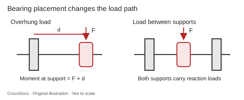
Draw the shaft's centerline and the points where external loads act. Then place the supports. A roller between two bearings usually loads the structure differently from a roller hanging beyond one bearing.
For a simplified shaft with supports 80 mm apart and a 20 N downward halfway between them, each support provides 10 N upward. If the same load acts 20 mm outside the left support, the reactions become 25 N upward at the left and 5 N downward at the right.
The second case creates a larger load at the nearby support and needs the distant support to resist the opposite direction. Moving the roller outward is therefore a structural change, even though the shaft still fits both holes. Actual shafts also see transmission forces, impact, and deflection.
Check how the parts fit
A bearing has an inner race around the shaft and an outer race in the housing. A flange or shoulder can locate it axially. Check the real drawing for bore, body diameter, width, flange, and corner .
Before making the plate, check these connections:
| Interface | What to check |
|---|---|
| Shaft to bearing | Bore size and profile, shaft , any step or shoulder |
| Bearing to plate | Housing diameter, fit, supporting thickness, |
| Shaft to hub | Matching round, hex, D, REX, keyed, or other shaft and hub shapes |
| Hub to mechanism | Bolt pattern, clamping length, screw access |
| stack | Spacer lengths, collars, shoulders, washers, and end screws |
A bearing for an 8 mm round shaft will not automatically support every nominally 8 mm shaped shaft. Likewise, a stepped shaft can use different bearing bores at different locations. Follow the supplier's assembly rather than replacing its with one assumed diameter.
Model a support plate
For a geometry exercise, a 60 × 50 mm plate on Front, with the lower-edge midpoint at the . Place a 16 mm opening at (0, 25) mm, and two 4.5 mm mounting holes at (−20, 8) and (20, 8) mm. the region 3 mm.
The 16 mm opening is a nominal practice seat. Before manufacturing a bearing housing, choose the actual bearing and a fit suited to the material and process. A nominally equal CAD diameter does not specify a press fit or guarantee a printed fit.
Insert two plate instances into an Assembly, parallel, with 80 mm between their inner faces. Use standoffs or other frame parts to set that gap. Put the bearing axes on a common line and add the chosen bearings.
Inspect a section through the shaft. Check which surface stops each bearing from moving in either axial direction. A flange stops movement in one direction; the rest of the mounting arrangement must handle the other direction where needed.
Lay out the complete stack
Work along the shaft from one end to the other. Include every component that occupies length, including collars, bearing projections, hub shoulders, pulley flanges, and washers.
For an illustrative 80 mm clear space, suppose bearing flanges occupy 1 mm at each inner face. That leaves 78 mm. A roller and hub taking up 50 mm, a pulley and hub taking up 12 mm, and 14 mm of spacers use 76 mm. You have 2 mm left to account for when choosing the final spacers and shims.
Use that remaining space to finish the assembly, rather than leaving the shaft free to slide by 2 mm. Choose spacers and retaining hardware that hold the shaft in place without binding the bearings.
Model the full outside length too. A pulley or collar outside the plate can collide with a wheel, field wall, or another mechanism. The shaft needs to reach far enough into its hubs and retaining hardware, but avoid leaving a long exposed end.
Check what gets clamped
For a live shaft, collars and spacers commonly contact the rotating inner races. A spacer with too large an outside diameter can rub a stationary outer race, seal, or housing. Inspect the contact in section rather than judging from an outside view.
For a , the axle stays fixed and the mechanism rotates around it. The inner-race spacing must let the axle be tightened without squeezing the rotating outer assembly. The path belongs to the rotating wheel or pulley, not to the stationary axle.
Use suitable hardware and the manufacturer's instructions. Tightening harder is not a repair for a stack that clamps the wrong parts together.
Align, then test
Locate both support openings from shared geometry. If you dimension them independently from different edges, small changes can make their axes disagree.
Before attaching the or transmission, assemble the supports and turn the shaft by hand with power disconnected. Tighten the structure progressively and check whether resistance appears. Then add the hub, retention, and transmission in stages.
A tight spot once per revolution suggests a different problem from a shaft that binds only after the plates are tightened. Check for a shaft or hub that wobbles as it turns, bent parts, misaligned supports, and spacers or collars rubbing the wrong surface. Record the final spacer arrangement in CAD before ordering replacement parts.