
Assemblies
Assemble two practice plates and two spacers, then check their position and freedom of movement.
Build a small from the plate in Parts and variables. You will use the same plate twice, with two spacers between them.
An is one use of a part. The two plate instances share one model: editing Plate changes both. A defines the allowed movement between two instances.
Make a spacer
Keep the existing Plate . Use the + menu at the bottom left to add a new Part Studio, and rename its tab Spacer.
- Start a on its Top .
- Draw two circles centered on the . Set the outside diameter to 10 mm and the inside diameter to 4.5 mm.
- Accept the sketch, then the ring-shaped region using Solid → New, Blind, 12 mm, in positive Z.
- Rename the part
Spacer.
You should have one hollow cylinder, with a hole through its full length. The 4.5 mm bore matches the practice plate's holes. These are for learning assembly placement; add suitable and material requirements before making a physical joint.
Insert four parts
Open the Practice assembly tab from Onshape. If you need a new Assembly tab, create one with the + menu.
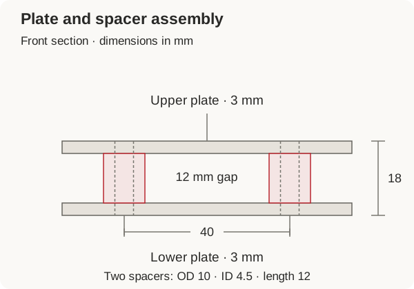
Choose Insert, select , and insert two instances of Plate and two of Spacer. Click in the workspace to place the instances apart so their faces are easy to select. You can place them anywhere for now; the mates will move them into place.
Rename the instances Lower plate, Upper plate, Left spacer, and Right spacer. These instance names identify their jobs without creating new part models.
Right-click Lower plate and choose Fix if it is not already fixed. This holds the lower plate still while you attach the other parts. Drag it to check: it should stay still. The other three parts should still be free to move.
Fasten the spacers
A is a reference point with axis directions. Onshape can infer one at the center of a circular edge. A Fastened mate removes all relative movement between its two connectors.
- Start a .
- On Lower plate, select the circular rim of the left hole on the top face. Check that the connector preview is at the hole center.
- Select the circular rim of the bottom bore of Left spacer. Rotate the view if you need to see it.
- Leave the offset at 0 mm. Check the preview: the spacer's bottom face should touch the plate's top face, and their holes should share an axis.
- If the spacer extends into the plate, flip the mate's primary-axis alignment. Accept when it stands above the plate.
- Repeat for Right spacer and the right hole.
Do not select the middle of the spacer's cylindrical wall. You need the connector at its end, so the two end faces meet.
Add the upper plate
Create one more Fastened mate. Select the top circular rim of Left spacer's bore, then the bottom circular rim of Upper plate's left hole. Use zero offset and adjust the alignment so the plate sits above the spacers.
The long edges of the plates should be parallel, with the right hole over Right spacer. If the second hole points the other way, rotate the mate connector half a turn about its primary axis using the mate’s rotation controls. Preview both hole locations before accepting. Do not add a second Fastened mate to hold the same upper plate: the first already fixes its relative position. If the other hole misses, check the part dimensions and selected connectors.
Taking the bottom face of Lower plate as zero height, the finished stack is:
| Instance | Bottom height | Top height |
|---|---|---|
| Lower plate | 0 mm | 3 mm |
| Both spacers | 3 mm | 15 mm |
| Upper plate | 15 mm | 18 mm |
Check the assembly
Measure 12 mm between the facing plate surfaces, 18 mm overall height, and 40 mm between spacer axes. Look through both holes from above. Drag each instance: none should move relative to the lower plate.
The instance list should contain two plates and two spacers. There should be three Fastened mates, and Lower plate should remain fixed. If a part floats, inspect its mate. If parts overlap, correct the selected end or alignment rather than adding another mate.
Choose Create in the document’s Versions and history tools and name it Practice assembly complete. Continue with Drawings and exports to document the plate and list the assembly's parts.
Moving mates
The practice assembly is deliberately rigid. A 's moving joints use other mates:
| Mate | Allowed movement | Robot example |
|---|---|---|
| Revolute | Rotation about one axis | Arm around a supported |
| Slider | along one axis | Slide carriage along its rail |
| Cylindrical | Rotation and translation along the same axis | A shaft that can slide along its axis as well as turn |
Translation means moving without rotating. For a moving mate, set the usable limits and inspect intermediate positions. You can animate a mate to check movement, but you still need to design the and look for collisions and snagged wires. Use Shafts and bearings and Robot packaging for those physical checks.