
Practice project
Bring the lessons together in a supported, belt-driven bench roller module.
Design a belt-driven roller between two side plates. You will plan its layout, model the custom parts, add hardware, assemble it, and prepare a drawing and parts list. This is a practice project you can build on. To use it in an or transfer, you will also need to work out the game-piece path and test the roller contact.
Complete the plate tutorial first, then use the relevant chapters as references. Create a separate Onshape document named Roller module practice, in millimeters.
Define the layout
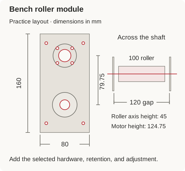
Use the plate's lower-edge midpoint as the side-view . Horizontal position runs across the plate; height runs upward. Begin with these teaching :
| Item | Value |
|---|---|
| Side plate | 80 mm wide, 160 mm high, 3 mm thick |
| Gap between inner plate faces | 120 mm |
| Roller | 40 mm diameter, 100 mm long |
| Roller axis | (0, 45) mm in side view |
| Simple shaft model | 8 mm diameter, 170 mm long |
| Simple model | 8 mm bore, 16 mm body diameter, 5 mm width |
| Simple model | 38 mm diameter, 60 mm body length |
| Motor axis | (0, 124.75) mm in side view |
The 79.75 mm separation between the axes comes from the illustrative 20/40-tooth, 2 mm-pitch, 220 mm pitch-length belt example. Use Transmission layouts to understand that choice.
Leave room for pulley flanges, hubs, and the motor connector too. Before making parts, replace these simple practice shapes with models or measurements of the hardware you will use, then check the fits and mounting holes.
Build the plate model
Make a named Side plate. its centered 80 mm width and 160 mm height on Front. Add the 16 mm bearing opening at height 45 mm.
For the dummy motor pattern, add a 20 mm central opening at height 124.75 mm, and four 4.5 mm holes at these positions:
(-12, 112.75)   (12, 112.75)
(-12, 136.75)   (12, 136.75)
Add four frame-mounting holes, 4.5 mm diameter, at X = −30 and 30 mm, with heights 15 and 145 mm. the plate region 3 mm, leaving the openings clear.
Keep the axis spacing and mounting patterns as named dimensions or variables. You can use the same plate twice for this learning . A later physical design may use different left/right features or a configured variant.
Make the simple parts
In separate Part Studios, model the roller, shaft, simple bearings, and spacers you will assemble along the shaft. Use concentric sketches and Extrude or as appropriate.
Give the roller an 8 mm nominal through bore for the geometry exercise. On a real , the roller must be attached to the shaft so they turn together. Use a suitable hub, clamp, shaped bore, or another connection that can carry the . A loose round hole will just let the shaft spin inside the roller.
Use a real motor and compatible pulley models when available. If you use the dummy motor, keep its mounting face and output axis clear and mark its part name as an . Use the actual motor drawing for screw depths and the actual pulley model or specification for tooth shape.
Assemble the supports
Insert two side plates and place their inner faces 120 mm apart. Use modeled standoffs or other structural parts to maintain that gap. Fix one plate for the practice assembly and Fasten the rigid frame parts to it.
Center each simple 5 mm-wide bearing model in its 3 mm plate, so it sticks out 1 mm on each side. Line up the two bearing axes. For a real build, include the bearing’s flange or shoulder, the correct fit in the plate, and something to hold it in place.
Place the 100 mm roller midway between the supports. With 1 mm inward bearing projections, the nominal space between them is 118 mm, leaving 18 mm around the roller for the appropriate spacer and arrangement. Look at a section through the shaft and choose spacers that fill the gaps without rubbing the stationary parts of the bearings.
Add the drive
the motor body to its plate. Place the driver and driven pulleys in the same belt with parallel axes. Check the shaft engagement, hub screws, collars, and the length available outside the bearing.
The 170 mm practice shaft sticks out 21 mm beyond each bearing’s outer face. Use that space to try placing the pulley, hub, and retaining hardware. Once you know their actual lengths and how much room you have in the robot, choose the final shaft length.
Give the shaft/roller assembly a relative to the frame. Fasten the parts that should turn together. If you model a drive relation, one driver turn should produce half a driven turn in the same direction for this open 2:1 belt pair.
Add a way to tension the belt without moving the roller axis. Check the belt's installation path and the motor's full adjustment range.
Review and document
Use Design review with a teammate. Check support alignment, rotation, retention, tension, tool access, and a route for removing the roller. Inspect the complete assembly, including the motor connector and mounting screws.
Make a drawing of the side plate, export its cutting profile, and create a . Identify which items you will make, which you will buy, and which are still simple placeholder models. Include the fastening and retention parts needed for a real build.
Create a named version Roller module review. Ask another student to find the shaft spacing, identify the torque path, locate the bearing retention, and explain the assembly order. Use their questions to correct the model and drawings before manufacturing.