
Shooter layouts
Lay out a flywheel, guide, object path, feeder, and supports before choosing the final launcher geometry.
Draw the game piece as it enters the shooter, touches the wheel and guide, and leaves the . Place the wheel, guide, feeder, and supports together, then check them from several views. Consistent shots depend on how the piece arrives and leaves as well as on wheel speed.
Use the Engineering flywheel guide for launcher behavior and the projectile mathematics guide for flight. Here, you will work out where the parts go and how they fit together.
Choose the contact arrangement
A single-wheel launcher may push the object against a curved or flat guide. Opposing wheels can provide a different contact and spin arrangement. Try the actual game piece and wheels in a , and check that you can release the piece from the position and angle you need.
Record wheel diameter, width, material, connection, and the guide's contact surface. Reserve the actual , , hubs, and transmission. Include how the game piece comes out of the transfer. It may arrive off-center or already spinning.
Draw a practice side layout
Create a document named Shooter layout practice, in millimeters. On Front, place the wheel axis at the and use:
| Item | Practice value |
|---|---|
| Wheel diameter | 96 mm |
| Ball diameter | 70 mm |
| Overlap in the model | 5 mm |
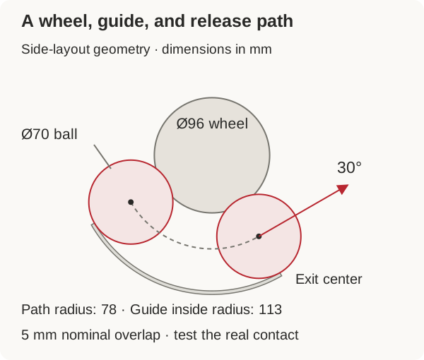
| Ball-center distance from wheel axis | 48 + 35 − 5 = 78 mm |
| Guide's inside radius | 78 + 35 = 113 mm |
Draw the 96 mm wheel circle. Add a construction circle of radius 78 mm for the ball-center path, and an arc of 113 mm radius for the inside guide surface.
Place 70 mm ball circles at several points along that path. Each should overlap the wheel circle by 5 mm and just touch the guide on the opposite side. This shows the gap in CAD. Use a prototype with the actual wheel and ball to choose how much squeeze works.
The guide-to-wheel gap is 113 − 48 = 65 mm, compared with a 70 mm object. Use the same when building the adjustable contact prototype.
Define the release direction
For this practice layout, let the ball-center path run from −150° to −60° around the wheel, measured counterclockwise from the rightward horizontal axis. That gives 90° of contact arc in the layout.
At the −60° endpoint, the ball center is approximately (39, −67.5) mm. A counterclockwise tangent there points 30° above horizontal toward the right. Draw that tangent as a construction line, then place ball circles along it to check that the ball has room to leave.
The tangent gives you a starting estimate of the shot direction. In a real shooter, deformation, slip, spin, and the guide’s final contact can change it. Measure where the ball actually goes before using the angle in your aiming code.
Check that the guide's end and nearby plates do not clip the departing object. The ball's center can clear an edge while the ball itself still strikes it.
Model a curved guide
For a simple guide-shape exercise, the 113 mm inside arc and a concentric 116 mm outside arc, spanning the chosen −150° to −60° sector. Join their endpoints with radial lines to make a closed 3 mm-thick strip.
the strip to a total 80 mm width, centered on the side-layout . You should have one curved guide wall. Use a separate for the wheel and its support components so the guide does not accidentally merge with them.
Add side guidance, mounting features, and the selected bearings and hubs in the complete . Check the actual wheel width and look from the front as well as the side. The ball may look centered in a side view while sitting off to one side of the wheel.
For an adjustable hood, include its pivot, the motor or that moves it, its travel limits, and any position or reference. Moving the hood can change where the ball leaves and how it touches the wheel, as well as the shot angle. Check the full range and the connection to the feeder.
Support the wheel
Place bearings and structure near the loads. Include the wheel hub, shaft , pulley or gear, and belt plane. Check the wheel's full outer , fastening hardware, balance requirements, and the manufacturer's permitted use.
Leave access to tighten the hub and replace the wheel. A compact launcher is difficult to maintain if its shaft cannot be withdrawn without dismantling the whole .
Estimate the required speed and loading using the selected components and test results. Choose the motor and with the wheel’s and recovery time in mind. Check that the motor can reach the speed you need under load and recover between shots.
Integrate the feed
Choose where the next game piece waits before entering the launcher and draw the gate or surface that holds it there. Check what the transfer rollers do while it waits. They must not keep forcing the piece into a closed gate until the motor overheats.
Agree with programmers on readiness, spacing between objects, and recovery after an incomplete feed. The feeder can limit throughput, and the launcher can limit the rate at which it produces consistent shots. Test them together instead of assigning the whole rate requirement to one subsystem.
Record the measured release position and useful settings with the model revision. Use Intake and transfer layouts for the incoming path and Design review before releasing the support and guide parts.