
Mechanism design
Lay out a transfer arm and check whether it delivers a game piece to the right place and angle.
A transfer has to put the game piece where the next can grab or guide it, facing the right way. In robotics, its position and orientation together are called its . A game piece can reach the right spot and still be too tilted for a claw to grab.
This example uses a simple pivoting arm and a rectangular practice object. Use a separate Onshape document called Transfer layout practice, with millimeter units. The engineering design process covers choosing requirements and ; this page works through the geometry.
Define the task
In a side-view , use horizontal distance for forward position and vertical distance for height. The example has:
| Quantity | Practice value |
|---|---|
| Arm pivot | (80, 100) mm |
| Pivot to object center | 120 mm |
| position | 30° below horizontal |
| Handoff position | 60° above horizontal |
| Object | 40 × 20 mm rectangle, with its long side parallel to the arm |
| Receiver opening | 44 × 24 mm, aligned with the handoff object |
These describe a geometry exercise, not a complete claw or a 's game piece. The arm must move through 90° between the two positions.
Draw the start and finish
- Start a sketch on the Front . Draw construction lines through the for the floor and horizontal reference.
- Locate the pivot 80 mm forward and 100 mm above the origin.
- Draw a 120 mm construction line from the pivot, angled 30° below horizontal. Its endpoint is the intake object center.
- Draw a second 120 mm construction line from the same pivot, angled 60° above horizontal. Its endpoint is the handoff center.
- At each endpoint, draw a centered 40 × 20 mm rectangle. Constrain its long sides parallel to that position's arm line.
- Add a centered 44 × 24 mm receiver rectangle at the handoff, with the same orientation.
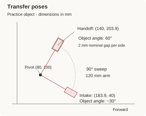
Measure the endpoints to check your sketch:
| Pose | Forward position | Height | Object angle |
|---|---|---|---|
| Intake | about 183.9 mm | 40.0 mm | −30° |
| Handoff | 140.0 mm | about 203.9 mm | 60° |
The coordinates come from pivot + arm length × (cos(angle), sin(angle)), with the calculator in degrees. Cosine gives the horizontal part of the arm's length; sine gives the vertical part.
If the next mechanism needs the block to arrive horizontal, this arm alone cannot do the job. You could turn the block earlier, add a wrist to the arm, or use a mechanism that keeps the block at the same angle as it moves. Hyperion's example shows how an team used transfer orientation to simplify its outtake.
Check the opening
With the 40 × 20 mm block centered in the 44 × 24 mm opening, there is 2 mm of space on each side. Keep its angle the same and move it 3 mm sideways, perpendicular to its long edge. One edge now extends 1 mm beyond the opening.
That block would catch on the edge. You could widen the opening, but check that the guides would still hold the game piece and leave room for the claw’s fingers. Try tilted positions too, and check from other views. Flexible wheels and game pieces will also behave differently from rigid shapes.
Build an adjustable version of the opening and feed game pieces into it from the actual intake. Try crooked and off-center pieces as well as neatly placed ones. Record which attempts work before choosing the final guide spacing. Use Transfers for contact, sensing, and recovery.
Share the dimensions and sequence
Share these and decisions with the teammate designing the next mechanism and the programmer:
| Interface | What to communicate |
|---|---|
| Arm mounting | Pivot location and axis, measured from the |
| Handoff | Object center (140, 203.9) mm and 60° orientation in this exercise |
| Receiver | Opening size, how far off-center a game piece can be, what holds it, and room for claw fingers |
| Sequence | When possible, have the second claw grip the game piece before the first lets go |
| Recovery | A return path that clears both mechanisms after a miss |
Sending a “close” command does not tell the code whether the claw has caught the game piece. Decide how a or tested delay will tell it when to move on.
Review before detailing
Move the block and arm through the full handoff. Add the nearby frame, intake, receiving mechanism, and cables to the sketch or . Check the movement back as well as forward. If you are unsure how the guides or claw will grip the game piece, make a small prototype and try it.
Only after that should you detail the plates, joints, and mount. Use Arms and linkages to size the load and support; the sketch tells you where the arm reaches and which way the game piece faces. You still need to calculate whether the can move the load.