
Curved and hollow parts
Use offset planes, Loft, and Shell to make an open funnel with a controlled wall thickness.
Use Loft to connect different profiles and Shell to hollow the resulting solid. This exercise makes a circular funnel, introducing tools useful for guides, ducts, and transitions between .
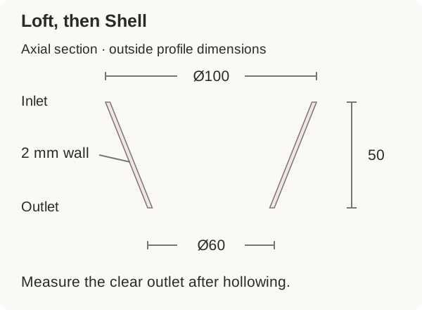
Create a separate document named Funnel practice, in millimeters. You will make one part with a 100 mm outside inlet, 60 mm outside outlet, 50 mm height, and 2 mm wall thickness.
Sketch the outlet
Start a on Top. Draw a circle centered at the and it to 60 mm diameter. Accept it and name the sketch Outlet outside.
This circle describes the outside of the part before it is hollowed. The clear opening will be smaller after Shell adds the inside wall. Keep that distinction visible when checking whether an object can pass through.
Add an offset plane
A reference lets you place a sketch at a chosen distance and angle from the rest of the model. Choose Plane, select Top as its reference, and use an Offset distance of 50 mm. Flip the direction if needed so the new plane is above Top, then accept.
Rename it Inlet plane. Start a sketch on that plane, draw a concentric 100 mm diameter circle, and name the sketch Inlet outside.
Look from the side. The two circles should be parallel, share an axis, and stand 50 mm apart. If they appear on the same plane, check the plane reference and offset before continuing.
Loft the solid
Accept both sketches, then choose Loft → Solid → New. Select the 60 mm circular region, then the 100 mm circular region as the profiles. Keep the ordinary end conditions for this straight transition and inspect the preview.
The result should be one tapered solid with flat circular ends. Accept it and name the part Practice funnel.
Loft follows the profile order. With several profiles, select them in the order the shape passes through them. A rectangle-to-circle transition can also need attention to how corners and connection points correspond. If the preview twists unexpectedly, inspect those connections instead of accepting the shape and trying to repair it with cuts.
Hollow it
Choose Shell and select both flat circular end faces for removal. Set the thickness to 2 mm, with the shell formed inward, then accept.
Rotate the model and look through it from each end. It should have an open inlet, an open outlet, and a continuous tapered wall. If one end remains closed, edit the Shell face selection. If the outside grows, check the shell direction.
Shell measures thickness perpendicular to the wall. Because this wall slopes, subtracting the inside radius from the outside radius in a horizontal section does not give exactly the wall thickness. Use a section view to measure how much room is left at the outlet.
Check an object
Make a separate for a 50 mm-diameter sphere to represent a ball. On Front, sketch a semicircle of 25 mm radius and close it with its diameter line. that closed half-circle region through 360° about the diameter, using Solid → New. Insert the sphere with the funnel into an and check the clear passage from inlet through outlet, including any mounting details you add later.
Start with the sphere on the funnel’s center axis, then move it off to the sides to check less tidy approaches. Look for places where it catches on the model. Test the real ball as well: friction, shape, and flexibility affect whether it will feed smoothly.
If the outlet is too small, edit the circle that defines it or change the wall thickness. Do not scale the finished funnel: that would also change its height, inlet, and wall thickness.
Add mounting features
Decide where the funnel will attach to the and how you will remove it for repairs. Add tabs, a supported rim, or a separate holder with appropriate . Keep mounting screws and nuts out of the object path.
For a tab made by Add, the tab must overlap the existing part so Onshape can join them. A sketch that only touches the funnel at one point may not create a valid joined solid. Inspect the preview and the Parts list; you should know whether you created one joined part or separate components.
Add where they help the loaded connection and the chosen process. Check the remaining material around holes and the tool path for tightening the fasteners. Use Fastened joints to design the complete attachment.
Prepare the print
Choose an orientation that balances supports, wall quality, mounting surfaces, and the object's contact path. Inspect the 's walls at both ends. A thin tapered edge should not disappear because it is too small for the selected process.
Print a small outlet or wall trial if fit and surface behavior are uncertain. Use the actual object to check passage before committing to the full guide. Name the sketches and Shell feature so you can find the opening sizes and wall thickness when you need to adjust them.
Use Printed parts for layer direction and fit trials, and Intake and transfer layouts to integrate the guide with the mechanisms on either side.