
Modeling features
Build a bracket, repeat its holes, and make a round spacer with a revolve.
A changes the model: an extrusion adds thickness, a cut removes material, and a rounds an edge. Choose the operation that describes the part's shape clearly. You will make an L-shaped practice bracket, then a separate round spacer.
Use a new document named Bracket practice, with millimeter units. This exercise leaves the original plate tutorial untouched.
Extrude a bracket
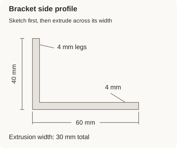
Start a on the Front . Use the sketch's horizontal and vertical directions as the coordinates below. Draw this closed outline, returning to the first point:
(0, 0) → (60, 0) → (60, 4) → (4, 4)
       → (4, 40) → (0, 40) → (0, 0)
Set the overall horizontal length to 60 mm, the height to 40 mm, and both legs' thickness to 4 mm. Use Horizontal, Vertical, Coincident, and to control it. The outline is an L in this side view.
Accept the sketch. its region using Solid → New, with a 30 mm symmetric extrusion centered on the sketch plane. The total width should be 30 mm, extending 15 mm to each side. Rename the part Practice bracket.
Check the result from an isometric view. You should see a 60 mm-long foot and a 40 mm-high upright, each 4 mm thick, across a 30 mm width. If you see two disconnected parts, inspect the corner where the legs meet.
This shape could represent a printed bracket or a part machined from solid material. A bracket made by bending sheet needs a bend radius and a flat pattern; use Sheet and machined parts for that workflow.
Cut and repeat the holes
Start a sketch on the foot's upper face. Place one 4.5 mm diameter circle, centered across the 30 mm width, with its center 20 mm from the outside upright face. Accept the sketch and Extrude Remove → Through all into the foot.
You can repeat that cut:
- Choose Linear in the toolbar.
- Set the pattern type to Feature, and select the hole's Extrude Remove feature.
- Select the foot's long straight edge for the pattern direction.
- Enter 25 mm between instances and an instance count of 2. The ordinary one-direction count includes the original hole.
- Reverse the direction if needed. The second center should be 45 mm from the same upright reference face.
- Make sure the bracket is selected as the part the pattern will change, inspect the preview, and accept.
You should have two holes, centered across the foot, with 25 mm between them. Increasing the instance count to three would place another hole at 70 mm, beyond the 60 mm foot. Use the preview to catch this instead of accepting a failing pattern.
Patterning a would make additional solid parts. Patterning this feature repeats cuts in the existing part. Choose the intended type before selecting geometry.
Hole types
Extrude Remove is useful for simple openings. The Hole feature also supports drilled, , tapped, , and definitions.
A counterbore is a larger cylindrical recess, often used for a screw head. A countersink is a conical recess for a matching countersunk head. A has an internal thread. These require the appropriate screw dimensions and enough material around and below the feature.
For a practice Hole feature, start a sketch containing a point at the required location, accept it, then choose Hole and select that point. Choose the type, size, start, end condition, and part scope. Inspect a section view to see the resulting depths. Leave enough material below a counterbore to support the screw head. A deep recess in a thin plate can remove most of that support.
Fillets and chamfers
A fillet rounds an edge with a radius. A cuts a bevel. They can remove sharp edges, provide a lead-in, or improve a shape for manufacturing.
On the bracket, try a 3 mm fillet at the internal corner where the foot meets the upright. Inspect the curved transition. Then try a 0.5 mm chamfer on an exposed outside edge, keeping the mounting faces and hole interfaces unchanged.
Add small finishing features late in the feature list. If a fillet fails, reduce its radius and check adjacent geometry. A large radius may consume a nearby face or collide with another edge. the finishing feature while repairing earlier geometry, then restore it.
An internal pocket cannot have a perfectly sharp corner when cut by a round end mill. A printed corner has different constraints. The manufacturing process determines which radii are useful; adding the same fillet everywhere does not solve every case.
Revolve a spacer
A turns a profile around an axis. Use it for a part described naturally by its section, such as a spacer, pulley blank, or stepped bushing.
Add a separate Part Studio named Revolve practice:
- Start a sketch on Front. Draw a vertical construction line through the for the axis.
- Draw a rectangle whose nearest edge is 4 mm from the axis, whose far edge is 8 mm from the axis, and whose height is 10 mm. Its bottom is level with the origin.
- Accept the sketch. Choose Revolve → Solid → New.
- Select the rectangle's region, then select the construction line as the revolve axis.
- Use a full 360° revolution and accept.
The result should be one spacer: 16 mm outside diameter, 8 mm inside diameter, and 10 mm long. The sketch distances were radii; the resulting diameters are twice as large. A rectangle that touches the axis would make a solid cylinder instead of an open bore.
Choose the simplest feature
Use Extrude for a constant cross-section, Revolve for a shape around an axis, Sweep for a section following a path, and Loft for a transition between sections. Begin with the simpler operations when they describe the part well.
Give each feature a clear job. A teammate should be able to find the foot thickness, mounting holes, and corner radius without working through one enormous sketch. Use CAD troubleshooting when a later feature breaks after an edit.