
Arms and linkages
Lay out pivots and four-bars, preserve a carried object's angle, and check actuator leverage.
Start by drawing what the arm carries and where it needs to go. Place the pivots and check the movement before drawing the links’ outlines. It is easy to change an outline later; moving a pivot can change where the whole reaches.
Use Mechanism design to practice planning a single arm’s movement. This page extends that work to linkages and placement.
A single arm
A rigid arm rotates everything attached to it by the same angle. If it turns 90°, a fixed claw on its end turns 90° too. That can be useful when you need to pick up a game piece at one angle and score it at another.
If the claw must keep a constant angle, you need another arrangement: a wrist actuator, a suitable linkage, a belt-driven orientation mechanism, or a different path. Decide which movements are actually needed before adding another .
Draw the arm when folded in, picking up, transferring, and scoring. Include the full shape of the game piece it carries. Check the return movement after release, when a claw or guide may be open instead of closed.
Draw a parallelogram
A four-bar linkage has four links connected by pivots, including the fixed frame. A parallelogram is a useful special case: opposite links have equal lengths, and the moving link, called the , stays parallel to the fixed link as long as the linkage stays in the same open or folded arrangement.
Create a separate document named Four-bar layout. On Front, draw using these pivot-center :
| Link | Length |
|---|---|
| Fixed link A–B | 80 mm |
| Left arm A–C | 120 mm |
| Right arm B–D | 120 mm |
| Moving coupler C–D | 80 mm |
Fix A at the and place B at (80, 0) mm. Start with both arms pointing up and right, at 30° above horizontal. C should be approximately (103.9, 60) mm, and D approximately (183.9, 60) mm.
Dimension A–B to 80 mm and A–C to 120 mm. Constrain B–D Equal and Parallel to A–C, with both arms on the same upward-pointing branch. Join C to D to close the loop. Its 80 mm length and horizontal orientation follow from those relationships; measure them as checks rather than adding duplicate driving constraints.
Dimension the angle between A–C and the horizontal reference to 30°. The endpoint positions should follow the linkage geometry rather than independent coordinate dimensions.
Change the angle to 90°. C should move to (0, 120) mm and D to (80, 120) mm. The coupler remains horizontal, but it has moved both upward and backward. A parallelogram preserves orientation; it does not automatically create straight vertical travel.
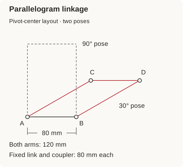
Choose the motion range
Try several intermediate angles and trace the object attached to the coupler. Check its corners, not only its center. Add the neighboring frame and to the .
Keep the layout on the intended branch, meaning the particular folded or open arrangement of the links. A crossed four-bar is a different geometric arrangement. A sketch that suddenly flips to the other branch needs better constraints or a travel range that avoids that transition.
At nearly straight or folded positions, a linkage can approach a singularity: its ability to move or resist forces changes sharply. Do not put a required handoff at such a position accidentally. Inspect the actuator's leverage and the real joints before choosing the end limits.
The links also need room in three dimensions. Separate layers with appropriate spacers, support the pivots, and account for screw heads. Lines can cross harmlessly in a side-view sketch while the actual links collide.
Check actuator leverage
A pushrod or servo linkage applies force along a line. The useful turning effect depends on its perpendicular distance from the driven pivot.
For a pushrod force , arm attachment radius , and angle between the arm radius and pushrod:
Suppose the arm needs 0.8 N·m, and the pushrod attaches 30 mm from its pivot. At a 90° angle, the required pushrod force is about 26.7 N. At 15°, it rises to about 103 N. The same attachment point can therefore be much less effective near one end of the motion.
Draw the servo horn, pushrod, and driven arm at several points in the movement. Check the horn’s full travel and the angles at both ends of the pushrod. A horn that gives plenty of reach in one position may have poor leverage, or be unable to reach, in another.
Model the joints
Use appropriate or bushings and retain the pins or . For a lightly loaded pivot screw, arrange the joint so tightening the does not clamp the moving link solid. For a loaded arm, support the shaft and structure according to the forces it carries.
Use Moving assemblies to represent the permitted motion. Avoid adding that constrain the same relationship twice. A closed linkage already connects its parts through several joints; a redundant can remove the movement you intended.
Add stops and references
Decide what physically limits the motion, how the finds its reference position, and what happens when power is removed. A tall arm may fall under gravity. A servo's command range is not a substitute for a well-supported joint or a safe stop arrangement.
Place where they observe a useful reference and remain protected through the movement. Leave room for their wires. Agree with the programmer on which position counts as zero, which direction increases the angle, and how far the arm can safely move.
Save three positions in the practice layout and show the space taken up by the game piece in each one. Use the Engineering arms guide for and support details, then the joint and actuator arrangement before making the complete mechanism.