
Design for manufacturing
Choose shapes, materials, and fits that your team can make, assemble, and replace.
A part that is easy to draw may be difficult to make. Design for manufacturing means choosing geometry with the actual tools, material, and process in mind.
Choose the process before finishing the model. A flat plate cut from sheet, a printed bracket, and a milled block each need different details.
Use stock sizes
Check what your team can buy before choosing thicknesses, lengths, or spacers. A 3 mm sheet and a 1/8 inch sheet are not the same thickness. That difference can matter in an axle stack or a tightly fitted assembly.
Model the stock you will actually use. Confirm material and thickness with the supplier, and measure critical stock when it arrives. If a part needs several machining operations to replace a readily available spacer, compare the effort with buying the spacer.
Flat plates
Flat plates work well when their important features can be cut from sheet and assembled with ordinary hardware.
Keep access holes distinct from mounting holes. Check screw-head and nut , distance from holes to edges, , and the structure joining loaded areas. A thin strip around a large opening may flex even though the model looks substantial.
With a rotating cutting tool, internal corners cannot be perfectly square. Choose a corner radius the available tool can make, or provide suitable relief where a rectangular part must fit. Ask the manufacturer what its process requires before changing the geometry.
Weight-saving cutouts
Pocketing removes material to reduce mass. A cut all the way through a plate is different from a shallow milled pocket; make sure your process can produce what the model shows.
Start by identifying the : where forces enter, where they leave, and which material carries them. Preserve support around bearings, , and crossmember mounts. Large openings can reduce and make a plate easier to twist.
Before copying cutouts from another , check how your plate carries its loads. Different bearing positions, material, or thickness can make the same pattern much weaker. Compare how much weight the cutouts save with how much the plate bends under load.
A cutout example
Suppose a 3 mm-thick plate carries a 100 N pulling between two sets of mounting holes. A large cutout leaves a narrow strip of material between them, called a web. Compare a 6 mm web with a 12 mm web, keeping thickness and load the same.
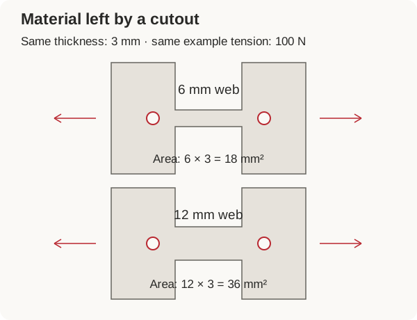
For this simplified direct-tension comparison, cross-sectional area is web height × thickness:
| Web | Area | Average tensile stress at 100 N |
|---|---|---|
| 6 mm | 6 × 3 = 18 mm² | 100 / 18 ≈ 5.6 N/mm² |
| 12 mm | 12 × 3 = 36 mm² | 100 / 36 ≈ 2.8 N/mm² |
The wider web halves the average stress for that load. This calculation does not include bending, sharp-corner stress concentration, or bearing loads, so it cannot establish a safe part rating. Round internal transitions for the chosen cutting tool, preserve material around fasteners, and test the actual loading direction.
In CAD, compare the uncut and cut profiles using the same material and thickness. Check mass properties, then make a simple load/deflection comparison on a . Keep a cutout when the mass saving is useful and the remaining structure meets the task.
Printed parts
Orient a print with the loads and layer directions in mind. Avoid placing a major separating load across a weak layer interface. Include space for fasteners and a practical way to install nuts or inserts.
Use small test pieces for uncertain fits. A bearing pocket, shaft opening, and screw hole need not all use the same allowance. Check printer, material, orientation, and settings before applying a result to the final part.
Allow adjustment where the needs tuning. Slotted roller mounts or replaceable spacers can make compression tests easier, provided the final joint can be locked securely.
Check the assembly
For each custom part, answer four questions:
- How is it made, and which matter most?
- How is it held and measured during manufacturing?
- How does it go into the robot, including its fasteners?
- How is it removed when damaged?
Then make one joint or a small test piece with the same fit. Measure it and try the actual hardware, adjust the model if needed, and only then make the full set.
Continue with Drawings and exports. For process details, use 3D printing, CNC and sheet parts, and Fits and tolerances.