
Custom drivetrains
Plan a parallel-plate FTC drivetrain around supported axles, available transmissions, and usable space.
A custom can free space for an or place where a kit cannot. It also makes your team responsible for axle alignment, support, tensioning, and replacement parts.
Keep a kit drivetrain when it meets your needs. Choose custom plates to solve a specific problem you can describe and test.
Start with the wheels
Choose the wheel type, diameter, wheelbase, and track width. Wheelbase is the front-to-back distance between axle centers. Track width is the side-to-side distance between wheel centers.
Draw the wheels and floor in the layout. Include the real width of the wheel, its hub, and the space needed by nearby plates. Check ground with the expected load and field surface.
wheels must be oriented correctly, and their rollers need room to rotate. Use Drivetrains for wheel arrangement and drive behavior.
Live and dead axles
| Arrangement | What rotates | Main design checks |
|---|---|---|
| The shaft turns with the wheel and driven pulley or sprocket | support the shaft; hubs transmit ; collars or clips retain it | |
| The wheel rotates around a stationary axle | Bearings are in the rotating assembly; the axle is secured; tightening does not clamp the rotating assembly solid |
Neither arrangement dictates which side of the wheel holds the transmission. Putting it outside the central space may help packaging, but it can increase width or make the transmission more exposed.
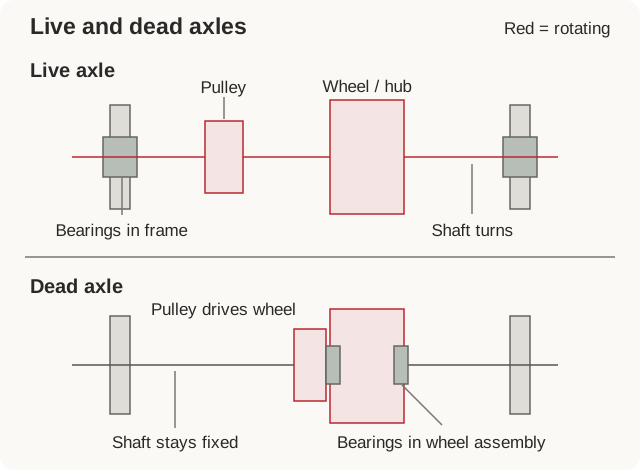
Before drawing side plates for a live-axle wheel, check how all the parts will fit together:
| Component | What it must match |
|---|---|
| Wheel and hub | Wheel bolt pattern, hub bore, and torque connection |
| Shaft | Hub bore, bearing bores, and hardware |
| Two bearings | Shaft diameter, plate seats, and flange/shoulder locations |
| Pulley or sprocket and hub | Shaft connection, belt/chain profile, width, and alignment |
| Spacers, shims, and collars | The races or shoulders they contact; clearance from rotating faces |
Make a section along the axle. For an illustrative 60 mm gap between inner plate faces, suppose each bearing projects 2 mm into the gap. That leaves 56 mm for the rotating assembly. A 28 mm wheel/hub , a 12 mm pulley/hub envelope, and 14 mm of spacers use 54 mm, leaving 2 mm unallocated.
You still have 2 mm to account for with the final spacers and shims. Do not leave the shaft free to slide back and forth by that amount. Add the hardware that holds it in place, then tighten the assembly and check that it turns freely. Make sure collars and spacers contact the intended rotating without rubbing the fixed housing.
For a real hardware study, the goBILDA Strafer hub-shaft 2110-0608-0002 uses an 8 mm-ID bearing and a 6 mm-ID bearing at different shaft locations, with shims and an end screw/washer. Its assembly instructions show why choosing bearings from one nominal shaft size can be misleading. Inspect that supplier stack before adapting its support geometry to a custom plate.
Fit the transmission
The transmission carries rotation from the motor to the wheel, using gears, a belt, or a chain. describes the spacing of its teeth or links; matching pitch alone is not enough if their profiles differ.
Pick real gears, pulleys, belts, or sprockets before fixing their centers in the plate. Tooth pitch, tooth profile, width, and available lengths must match.
For compatible standard spur gears, the nominal center distance is:
Here is module, the metric measure of tooth size, in millimeters. are tooth counts. Two illustrative module-0.8 gears with 20 and 40 teeth have a nominal center distance of 24 mm. Confirm the manufacturer's requirements, including and any profile changes, before using that .
For a timing pulley, pitch diameter is , where is belt pitch. A layout circle should represent this pitch diameter, not automatically the outside of the teeth or flange. Matching circles does not prove that a belt of the required length exists.
Plan tension adjustment and tool access. A belt that can only be installed by bending the frame is an assembly problem. Excessive tension can overload bearings and bend plates.
Belt spacing
Use the side layout from Layout sketches. Its example transmission has a 20-tooth driver, 40-tooth driven pulley, and 2 mm belt pitch. The is 40/20 = 2:1: the wheel shaft turns once for every two motor-output turns.
The pulley pitch diameters are approximately 12.73 mm and 25.46 mm. A 220 mm pitch-length belt has 220 / 2 = 110 teeth. With this belt, the two-pulley geometry gives a center distance of about 79.75 mm. A pitch length measures around the belt's working pitch line, not its outside surface.
Use a calculator for the selected belt profile and pulley sizes, then confirm the manufacturer's installation and tension requirements. Include adjustment without shifting the wheel axes out of alignment. Rounding the center distance to 80 mm changes the fit of that 220 mm belt, so include enough adjustment to tension it correctly.
In the practice layout, the front wheel axis is 52 mm above the floor, so the motor axis goes at 52 + 79.75 = 131.75 mm. If you move the motor, update the shared layout so everyone sees the new belt route and the room it needs in the chassis.
Design the plates
Locate axle centers and motor mounts from the shared layout. Add crossmembers or standoffs that keep the two plates parallel under load.
Leave material around bearing seats and attachment points. Draw the likely force path from wheel contact through the axle supports into the frame before adding weight-saving cutouts. Read Design for manufacturing before pocketing the plate.
Prototype one side
Check one drive module before cutting the whole chassis. Verify that it assembles, rotates freely, tensions correctly, and can be serviced. Then test straight driving, turning, braking, and simultaneous use on the complete robot.
The Pretty Smart Robotics example shows how one team separates the side plates, motor assembly, and wheel assemblies into manageable design tasks.