
Layout sketches
Plan an FTC robot with shared references before detailing individual parts.
A layout is a simple drawing of where important parts will go. It can show wheel centers, pivots, game pieces, and the space needed by each without modeling every bracket.
Use it to check how mechanisms fit together. Can the reach the floor? Will the lift clear the battery? Where will the intake pass the game piece to the next mechanism?
Choose references
Pick a and axis directions that the whole team can explain. One possible convention is an origin on the floor below the center, with X forward, Y left, and Z up. Record your choice and agree with the programmers how it relates to their coordinate system.
A is a reference used to locate other geometry. Good robot datums include a chassis center , a mounting surface, and a wheel axle. Use references that are unlikely to disappear when a decorative edge changes.
Draw the robot in simple views
Make a named Robot layout. Begin with a side view and a top view. Add a front view when side-to-side spacing matters.
- Mark the floor and the current 's relevant size limits.
- Place wheel centers and the outside of the chassis.
- Draw the game piece and the field feature it must reach.
- Add the major intake, transfer, and scoring positions.
- Reserve space for , battery, hubs, connectors, and wiring.
The side view explains height and reach. The top view catches problems that the side view hides, such as a motor occupying the same width as a lift rail.
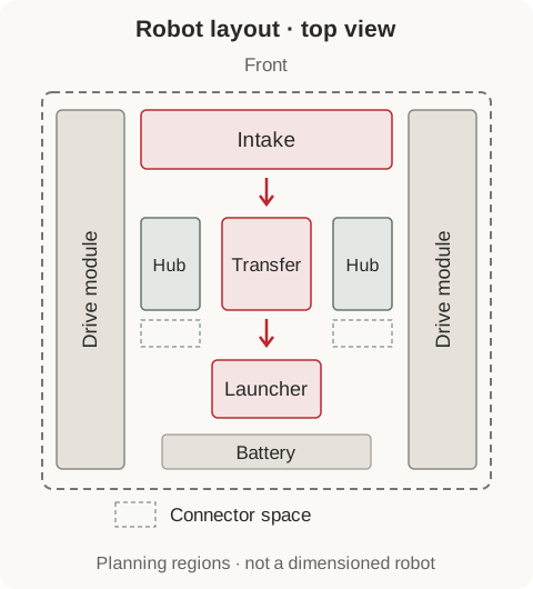
The colored areas reserve space while you plan. Replace them with your robot’s , and check the game’s size and extension rules in each position.
Define the game-piece path
Draw the game piece where you pick it up, pass it between mechanisms, hold it, and score it. Include the surfaces that hold it up along the way.
For a claw-to-claw transfer, draw both open claws and the game piece between them. For balls, draw the rollers, guides, and any gate that stops them. Show what actually moves the game piece between mechanisms; an arrow between two boxes leaves that question unanswered.
Use a to choose the gap between rollers or guides. Try actual game pieces to see how much the wheels compress and where each piece comes to rest. A model of the standard game-piece dimensions cannot tell you that on its own.
A drive layout
Create a separate document called Drive layout practice. This example is independent of the plate . Use millimeters and rename the first Part Studio Layout.
Add these Length variables before making the sketch: frontX = 80 mm, wheelbase = 200 mm, wheelRadius = 52 mm, and centerDistance = 79.75 mm. Wheelbase is the distance between the front and rear wheel axes.
On the Front plane, make a sketch named Wheel positions. Treat horizontal distance as forward position and vertical distance as height above the floor. Draw a construction line through the origin for the floor.
| Item | Horizontal position | Height | Diameter |
|---|---|---|---|
| Front wheel | #frontX | #wheelRadius | 2 * #wheelRadius |
| Rear wheel | #frontX + #wheelbase | #wheelRadius | 2 * #wheelRadius |
| Motor | #frontX | #wheelRadius + #centerDistance | 38 mm |
Make the circles . Dimension their centers from the origin so they cannot drift. The wheel centers should be at (80, 52) and (280, 52) mm. The motor-envelope center should be at (80, 131.75) mm.
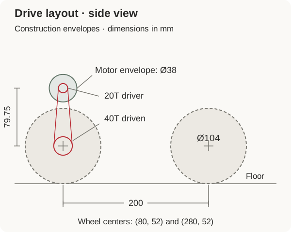
The nominal gap between the 38 mm motor envelope and the 104 mm wheel is 131.75 − 19 − 104 = 8.75 mm in this view. A top view is still needed to check their widths and mounting hardware. The custom drivetrain example explains the chosen transmission center distance.
Share the layout
Once the important positions make sense, use Onshape's feature to bring the relevant layout sketches into the Part Studios that need them. Reference their geometry when locating mounting features.
Use the practice layout to make a dependent plate:
- Add a Part Studio named
Side plate. - Choose Derived → , select the
Wheel positionssketch from Layout, and accept. Keep the base-origin placement so the references stay aligned. - Start a sketch on the same Front plane. Use Use to project the two wheel circles, and make the projected circles construction geometry if they are not already dashed.
- Draw a 14 mm circle concentric with each projected wheel circle. Concentric keeps the two centers together when the source moves. The 14 mm circles are practice openings; choose the actual housing fit from your bearing's requirements before manufacturing.
- Draw a rectangle with its lower-left corner 30 mm forward of the origin and 30 mm above it. Make it 300 mm wide and 140 mm high. Accept the sketch and its plate region, excluding the two holes, as a New 3 mm-thick part.
The part should have two openings 200 mm apart, derived from the layout rather than independently positioned. Hide the Derived geometry to inspect the solid, then show it again when checking alignment.
Have each mechanism use positions from the layout, and have its individual parts use those same references. Avoid a circular dependency in which the layout depends on a plate that already depends on the layout. Linked documents and pinned versions may require an explicit update; check which state a derived reference uses.
Try a change
In Layout, change wheelbase from 200 to 220 mm. The rear wheel center should move from X = 280 to 300 mm. In Side plate, its concentric opening should follow, while the front opening stays at X = 80 mm.
If the hole stays behind, check the Derived reference and Concentric constraint. If the reference is pinned to a version, update that reference deliberately. Restore 200 mm when finished. Inspect the remaining edge material and neighboring components after any layout change.
Keep the layout readable. Name sketches by their job, hide unused references, and leave the detailed outlines of plates in their own Part Studios. Add detail to the layout only when it helps decide an important location.
Next, check the design in three dimensions with Robot packaging.