
Drawings and exports
Make a drawing, export the practice plate, and produce a parts list for its assembly.
Use the 70 × 40 × 3 mm Plate from Parts and variables. You will make a dimensioned drawing and export its shape. If you completed Assemblies, you can also produce a four-part .
Choose the file
| Format | What it carries | Typical use |
|---|---|---|
| Solid geometry | Sharing with another tool or a machinist | |
| A flat profile | Cutting a sheet part | |
| or 3MF | A surface mesh, made of small flat faces | A supported 3D-printing workflow |
| PDF drawing | Views, , and notes | Communicating requirements and checking a part |
| Table values | Purchasing or reviewing a parts list |
Keep the editable Onshape document. Exported geometry does not preserve its original feature history. Ask the recipient which format their process accepts.
Make a plate drawing
- Open the Plate . In the list, right-click Plate and choose Create drawing of Plate.
- Choose a millimeter drawing template with a suitable sheet size, such as A4. Use Suggested views to begin with views of the part.
- Keep a face-on view that shows both holes and an edge view that shows thickness. Delete redundant views if they crowd the sheet. Move the views apart before adding dimensions.
- Use Dimension to show the overall 70 mm width, 40 mm height, and 3 mm thickness.
- Dimension a hole to 4.5 mm diameter and add a note that it applies to both through holes.
- Locate the first hole center 15 mm from the left edge and 20 mm from the bottom edge. Show 40 mm between centers. That is enough to locate both holes without adding dimensions that repeat the same information.
- Add the part name and a revision, such as
Plate — r1. Check the drawing's displayed units and scale.
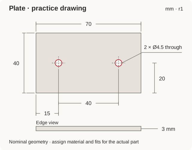
For an actual manufacturing order, add the chosen material, stock thickness, quantity, and functional . A seat needs a different fit decision from a loose screw hole. Use Fits and tolerances to establish those requirements with the fabricator.
Right-click the drawing tab, choose Export, and select PDF. Open the downloaded PDF and check that dimensions, notes, and the title block are legible. A drawing scale changes how a view appears on paper; its dimension values still describe the real part.
Export the plate
For a 3D-printing trial:
- Return to Plate and right-click the part in the Parts list, not the . Choose Export.
- Select STL, Millimeter, and a suitable mesh resolution. Use a filename such as
practice-plate-70x40x3-r1.stl. - Open it in the intended printer's . Confirm 70 × 40 × 3 mm and two open holes before choosing print settings.
For a flat cutting profile, right-click the plate's large planar face and choose Export as DXF/DWG. Select DXF and millimeters. Exporting the face gives its outside boundary and hole boundaries without the drawing's annotations.
You can download a reference DXF to compare with your result. It is an original 2D profile of the same practice geometry: one 70 × 40 mm closed rectangle and two circles of radius 2.25 mm. It is not a substitute for your editable model.
Open the DXF in the receiving tool and measure 70 mm across the outline and 40 mm between circle centers. If the size is wrong, correct the import/export units before cutting. Confirm whether the fabricator applies or tool compensation; avoid applying it twice.
Build a parts list
A bill of materials, or BOM, lists the parts and quantities in an . Open Practice assembly, then select the BOM Table icon on the right side of the Assembly workspace.
Choose Flattened to combine repeated instances. Add the Name column if needed. For this exercise the list should contain:
| Part | Quantity | Geometry |
|---|---|---|
| Plate | 2 | 70 × 40 × 3 mm; two 4.5 mm holes |
| Spacer | 2 | 10 mm OD, 4.5 mm ID, 12 mm length |
OD means outside diameter; ID means inside diameter. The two plate instances count as two of the same part, not two separately designed parts. If the count is wrong, check the Assembly instance list.
Fill in part numbers and descriptions through each part's Properties. For practice, names such as PLATE-001 and SPACER-001 are enough; purchased components need their actual supplier part numbers.
Use the BOM table's three-dot menu → Export to CSV. Open the CSV in a spreadsheet and check the two quantities. The reference parts list shows those two plates and two spacers. Add real and assembly supplies before treating a BOM as a complete build order.
Revision files
Create a named version after accepting the final geometry. Keep the exported profile, 3D model, drawing, and BOM tied to that version. If a hole moves later, update the affected drawing and exports before someone makes the old plate.