
Sketches
Use dimensions and constraints to make a mounting pattern that stays correct when edited.
A describes geometry on a flat . set sizes and distances. set relationships: two lines stay parallel, two circles share a center, or a point stays on a line.
Start in the empty Plate from Onshape. If you already made a practice solid while exploring, use a new empty Part Studio for this sequence. You will finish this page with one sketch and no solid parts.
Decide which sizes and relationships should stay the same when you edit the part. For example, widening a plate should not change the spacing of holes that fit an existing .
Dimensions and constraints
| Tool | Example on an part |
|---|---|
| Coincident | Put a hole center on a construction line |
| Horizontal or vertical | Keep the edge of a plate aligned with the sketch axes |
| Equal | Give two mounting holes the same diameter |
| Symmetric | Keep holes equally spaced around the center of a bracket |
| Concentric | Keep a seat centered on a opening |
| Tangent | Join a straight guide to a curved section without a corner |
helps you line things up without becoming part of the outline you will . For example, a centerline can keep a row of mounting holes straight without dividing the region you will extrude.
A two-hole plate
These are practice dimensions, not a vendor mounting pattern. All dimensions are in millimeters.
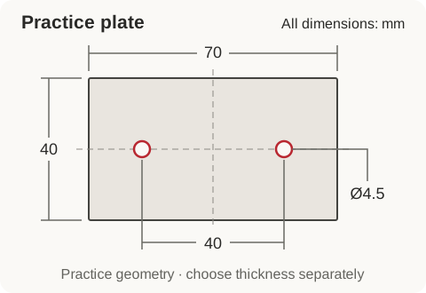
- Create a sketch on the Top plane.
- Draw a center-point rectangle with its center at the . Dimension it to 70 mm wide and 40 mm high.
- Add a horizontal construction line through the origin.
- Draw two circles with their centers on that line.
- Put one center 20 mm left of the origin and the other 20 mm right. Dimension each center horizontally from the origin; use 20 mm for both. Keep the circles on opposite sides.
- Dimension one circle to 4.5 mm diameter and make the other equal.
To add a size, choose Dimension, select the edge or circle, place the dimension, and enter its value. To locate a hole horizontally, select its center and the origin, then place a horizontal dimension. Keep the left center left of the origin and the right center right of it. Both distances are 20 mm.
For Equal, select the two circles and apply the Equal constraint. Their centers remain separate; their diameters are linked. Rename the sketch Plate outline.
The hole centers are now 40 mm apart. That leaves 15 mm from each center to the nearest short edge. These dimensions describe the geometry; whether this plate can carry a particular load is a separate engineering question.
Check what can move
A is an independent way that geometry can still move or change. A circle might have a defined diameter but an unfixed center.
Drag a line or circle gently while the sketch is open. If something moves that should stay in place, look for the missing dimension or constraint. Onshape normally shows under-constrained geometry in blue and fully constrained geometry in black; also inspect the constraints and solver messages rather than relying on color alone.
Do not use Fix on every entity just to make everything black. That can preserve accidental mouse positions instead of the dimensions you meant to specify. Fix is useful for deliberately locked geometry, but dimensions and relationships are usually clearer for a part you will revise.
Test an edit
Change the plate width from 70 to 80 mm. The holes should remain centered and 40 mm apart. Undo that change, then alter the hole spacing. The outside width should stay at 70 mm. Undo the spacing change too. Before continuing, confirm 70 × 40 mm overall, each hole center 20 mm from the origin, and both holes 4.5 mm in diameter.
If the wrong geometry moves, revise the constraints now. This small check is much easier than finding a shifted mounting hole after manufacturing.
Common problems
- The sketch turns red: inspect conflicting dimensions or constraints. Remove the redundant relationship rather than adding more.
- A region will not extrude: look for a small gap, duplicate line, or construction edge where a real boundary is needed.
- An unexpected constraint appears: Onshape can infer relationships while drawing. Inspect what was added before accepting it.
- A dimension cannot drive the sketch: it may be a reference measurement, already determined by other dimensions.
Accept the sketch. The feature list should contain Plate outline, and the Parts list should still be empty. Continue in this same Part Studio with Parts and variables.